 Facebook
 Google
 GitHub
 Linkedin
Hi folks,
This is my first post on AAC but I am not sure if this question is in the correct section (apologies if it isn't) and I am hoping I will get the answer I need.
I am quite new to the world of electronics and especially schematics. I have built a 4x4x4 RGB cube that I found on Instructables but everything had been done for me, even the Arduino code.
Now I want to design my own pcb for an 8x8x8 RGB cube based on the now infamous Kevin Darrah's cube, but I don't much like the idea of 192 transistors and 704 resistors to drive the led's.
I know that I can use the ULN2803 instead of the 2N3904s and resistor networks instead of the 704 resistors.
The programs I want to use to design the pcb are old but pretty easy to use, LiveWire and PCBWiz (unless anyone can suggest another easy to use pcb design program). I have thought about using EagleCAD or Fritzing but they are both a bit much for my limited pcb and pc knowledge, and I can't find all the parts I need in either of their parts databases.
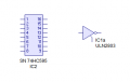
My questions are >- How do I connect the SN 74HC595 symbol (with 8 output lines) to the ULN2803 symbol (with 1 input line) on a schematic,

and where do I connect the 8 outputs, the GND and Common +V with only 2 lines remaining ?
This is probably the most important piece of info I need and my 2 days searching have come to nothing.
Please help in any way if you can, all info will be looked into and will be gratefully received.
Thanks, in advance, to all who reply.
This is my first post on AAC but I am not sure if this question is in the correct section (apologies if it isn't) and I am hoping I will get the answer I need.
I am quite new to the world of electronics and especially schematics. I have built a 4x4x4 RGB cube that I found on Instructables but everything had been done for me, even the Arduino code.
Now I want to design my own pcb for an 8x8x8 RGB cube based on the now infamous Kevin Darrah's cube, but I don't much like the idea of 192 transistors and 704 resistors to drive the led's.
I know that I can use the ULN2803 instead of the 2N3904s and resistor networks instead of the 704 resistors.
The programs I want to use to design the pcb are old but pretty easy to use, LiveWire and PCBWiz (unless anyone can suggest another easy to use pcb design program). I have thought about using EagleCAD or Fritzing but they are both a bit much for my limited pcb and pc knowledge, and I can't find all the parts I need in either of their parts databases.
My questions are >- How do I connect the SN 74HC595 symbol (with 8 output lines) to the ULN2803 symbol (with 1 input line) on a schematic,
and where do I connect the 8 outputs, the GND and Common +V with only 2 lines remaining ?
This is probably the most important piece of info I need and my 2 days searching have come to nothing.
Please help in any way if you can, all info will be looked into and will be gratefully received.
Thanks, in advance, to all who reply.
Attachments
-
 3.1 KB Views: 28


