SMPS repair

Thread Starter

drjackool

Joined May 23, 2021
62
Hi
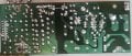
I have a SMPS thats not works (full off. Just voltage on main capacitor is ~300VDC) even by replacing PWM chip and TL431 and optocoupler. Also I tested FET and it is healthy. Also when measuring IC supply voltage it is about mili-volts. My question is there are a way to place a temporary resistor instead optocoupler to keep PWM On and removing unnecessary elements (specifically output side of transformator) to trace the problem?
Thanks
20260120_140418.jpg
 

Attachments

Last edited:

MrChips

Joined Oct 2, 2009
34,628
SMPS are difficult to trouble shoot even if you have the circuit schematics.
But the first step is to find the schematics.
 

B-JoJo-S

Joined Jan 3, 2026
211
voltage on main capacitor is ~300VDC
That only means the cap is rated for voltages up to 300 volts DC.
when measuring IC supply voltage it is about mili-volts.
I've not seen an IC that works on mV. If your IC is not getting power then that's a start. Trace back where the power comes from. And if you can't find or don't have a schematic - start making one.

One of the first MOST fundamental checks is the fuse. Is it good or blown. If it's blown then something caused it to blow. Before fixing the fuse you will have to determine what else is wrong.
 

Irving

Joined Jan 30, 2016
4,996
If voltage on main capacitor is 300v but that on controller is only mV then that's an obvious issue. Normally there's a large value resistor (100k - 300k typically) from the HV supply to the chip just to get it started and this is supplanted by a feed from an auxiliary winding of the transformer via a diode. Could be resistor is o/c or diode is s/c. Also there's usually a small low voltage electrolytic from chip supply to ground that can go s/c
 

Rockettfuel

Joined Sep 17, 2025
29
Yea its best not to rig the IC to bypass a fault that can definitely cause more damage if not addressed first. I would test the resistance of the resistors on the high-side by first looking up the color codes of each one. And if any are out of tolerance then they should be replaced. Similar to what was already mentioned above I would follow the traces to help pinpoint the fault.
 

Irving

Joined Jan 30, 2016
4,996
This module, SAO-0255A was, it seems, bought in and widely used in TV broadcast satellite receivers, distribution amps and other similar low power uses. You can actually still buy them from at least 2 suppliers on Alibaba for a couple of USD, as long as you buy a minimum of 1000! But, sadly, so far no schematic found at the usual locations.

What is the controller chip U1? Knowing that will give a pretty good idea of the front end schematic...

Looking at the discoloration on that transformer, I'd certainly wonder about its integrity...
 

Pyrex

Joined Feb 16, 2022
501
Hi,
as it was already mentioned, replace those bulged electrolytic capacitors first.
Check three big diodes located near to the transformer for short.
Find controller U1 datasheet. Find the typical controller application circuit in the datasheet. It is very likely that your SMPS will match this circuit , at least on the primary side of the transformer
 
Top