Facebook
 Google
 GitHub
 Linkedin
Hello,
I have a little problem.
I chose a project for school which I've managed to get working...
All the circuitry before and after the SMPS is working properly,
my only concern here is, that the SMPS is only working at an efficiency of around 54%.
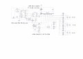
I've added my schematics for the SMPS part... feel free to use it even though its not good")
I would apriciate any help or suggestions to bump the efficiency higher!
Ps. I can't feel any heat beeing generated... so where am I loosing all the power???
PPs. Sorry for my bad english, it's a bit rusty even though I'm 19...
125339[/ATTACH]
I have a little problem.
I chose a project for school which I've managed to get working...
All the circuitry before and after the SMPS is working properly,
my only concern here is, that the SMPS is only working at an efficiency of around 54%.
I've added my schematics for the SMPS part... feel free to use it even though its not good
I would apriciate any help or suggestions to bump the efficiency higher!
Ps. I can't feel any heat beeing generated... so where am I loosing all the power???
PPs. Sorry for my bad english, it's a bit rusty even though I'm 19...
125339[/ATTACH]
Attachments
-
 76.2 KB Views: 36