SMD LED - trying to identify/determine equivalent in another color

Thread Starter

Taymar

Joined Jan 13, 2017
34
You're absolutely right, I apologize. It quickly became apparent that I'm way out of my depth here.

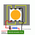
my 'after' goal is simply to replace these LEDS with a different color temperature version without having any adverse effects on the circuit. You're completely correct in that I have no idea what's in there now.

Would it work if I annotate the values showing where I connected the multimeter probes? I am guessing that I need to measure across each component, but if that's not correct please could you advise on how I should measure?

thank you again for your patience.
 

Thread Starter

Taymar

Joined Jan 13, 2017
34
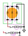
I have annotated the diagram with measured voltages, fresh measurements using a new multimeter and a benchtop power supply at 12v.

Please excuse the crude cut & paste job - the copy of the lower rail at the bottom was to illustrate the current I measured for the circuit (running the multimeter in series at the power supply).

If there are any other specific points I need to measure, please don't hesitate to let me know.

Thank you again for the continued help.

voltagescurrent.jpg
 

LesJones

Joined Jan 8, 2017
4,509
The first diagram with the LEDs in makes sense. With 2.4 volts drop across 150 ohms the current would be about 16 mA. You seem to have lost 0.6 of a volts somewhere, Maybe there is a diode in series that you have missed.
The bottom diagram showing a current of 72 mA through the 150 ohm resistor does not make sense. That would produce a voltage of 10.8 volts across the 150 ohm resistor. It would also mean that 0.78 of a watt was being disipated in the resistor which would make it quite hot.
I think I would just buy some of the 5050 LEDs that contain 3 LEDs and are rated at 20 mA per LED. I suspect the connection to the unit marked PWM could be for dimming the lights.

Les.
 

Thread Starter

Taymar

Joined Jan 13, 2017
34
Thank you Les,

I wish this circuit were easier to trace. Could the voltage loss be coming from either D5/D7, or from the switch itself? The switches are quite large and get pretty warm when the circuit is on.

I hope I didn't screw up the current measurement - I connected the multimeter in series between the power supply and the + voltage input on the circuit board, switched one LED on and got a reading of 72ma. I'd be curious to know what I did wrong here. I literally broke the circuit to measure the current, didn't measure it across the resistor.

The yellow wire seems to be tied into the vehicle's headlights. When the headlights are on, the yellow wire receives voltage and this controls the other tiny SMD leds on the board, which light up the push switch bezel. The blue wire (PWM) appears to receive the door open signal and switches all the lights on. The other red wire marked PWM (and the black wire to the left of it) power a separate small regular bulb in the overhead light unit.
 

LesJones

Joined Jan 8, 2017
4,509
You would have been measuring the total current taken by the board. The 0.6 volts drop will not be caused by a switch but it fits with the forward voltage drop of a silicon diode. I can not see the tracks on the board to follow them from the 150 ohm resistor. I think tracing the circuit would be more for the satisfaction of understanding exactly how it works rather than changing our viw of the required LED rating.

Les.
 

EM Fields

Joined Jun 8, 2016
578
I have annotated the diagram with measured voltages, fresh measurements using a new multimeter and a benchtop power supply at 12v.

Please excuse the crude cut & paste job - the copy of the lower rail at the bottom was to illustrate the current I measured for the circuit (running the multimeter in series at the power supply).

If there are any other specific points I need to measure, please don't hesitate to let me know.

Thank you again for the continued help.

View attachment 118929
 
@Taymar I'd bet dollars to doughnuts those LEDs you linked in your last post will work just fine. I think a lot of the work you did here was mostly learning experience... once we found out the dies were connected in series @ 3V apiece, chances were it was a common 5050 3-die LED designed to run at 3V/20mA per die.

The datasheet off that link there is very explicit and indicates the power dissipation and current as per-die (i.e. 3x120mW and 3x20mA respectively), so you know they're not expecting you to run the whole thing at <120mW and/or that each die is only 6.7mA. You can probably get PLCC-6 5050 LEDs cheaper on eBay, but their specs there are sometimes flaky, and unless you buy from a slow-boat Chinese seller it's not going to be significantly cheaper (and will take much longer to get to you).
 

Thread Starter

Taymar

Joined Jan 13, 2017
34
Thank you very much! Yes, this was most definitely a learning experience... Pretty interesting stuff; I intend to dig into this circuit a bit deeper as I'd love to understand the functions of the whole thing.
 

Thread Starter

Taymar

Joined Jan 13, 2017
34
I've swapped out one of the LEDs with these ones: https://www.superbrightleds.com/mor...ewing-angle-6000-mcd/316/#/tab/Specifications

and have just one more question I'm afraid.

The new one has a larger voltage drop across it, by around 2v total. It's MUCH brighter than the old one, though at 14.4v supply, the drop across the LED die is right at the max voltage specifications for the LED. The circuit also gets fairly warm with this new one.

Is there any reason why I can't simply add another resistor in series with the LED to dial it back a bit? I've bench tested this and seems to achieve the desired result, but as you've probably guessed by now, I have very little idea what I'm doing.

Color temp is perfect by the way, thank you for the recommendation.

thank you
 

LesJones

Joined Jan 8, 2017
4,509
I would think adding a series resistor would probably be OK but to be sure we would need to see the schematic of the drive circuit. The current through the LED array is the value that you should be cheching to make sure you are not exceeding it's rating. If the voltage across the new LED is higher than the original I would expect the driver circuit to run cooler than with the original. It looks like our guess that the current was just limited by resistors is wrong.

Les.
 

Thread Starter

Taymar

Joined Jan 13, 2017
34
Thank you Les. Would you mind telling me the correct way to measure the current through the LED array please?

I will take another stab at tracing the circuit also.

Thank you!

I would think adding a series resistor would probably be OK but to be sure we would need to see the schematic of the drive circuit. The current through the LED array is the value that you should be cheching to make sure you are not exceeding it's rating. If the voltage across the new LED is higher than the original I would expect the driver circuit to run cooler than with the original. It looks like our guess that the current was just limited by resistors is wrong.

Les.
 

LesJones

Joined Jan 8, 2017
4,509
Disconnect the connection to either end of the LED Then connect via a multimeter set to a current range (From memory I think the rated current was 20 mA Check the value on the data sheet.) A suitable range would be 100 mA The meter now being in series with the LED will show the current flowing THROUGH the LED. Do not worry if the meter shows a negative reading. It is just the magnitude of the current that you are interested in.

Les.
 

Thread Starter

Taymar

Joined Jan 13, 2017
34
Yes, the rated value for the new LEDS was indeed 3x20mA (3 dies per LED, wired in series in this application).

As I was hooking it up, I spotted that I had a short between two pins on the old LED. I corrected this and the readings are now much closer. Voltage drop across leds appears to be within spec, but the current at 14.4v worries me as it's pushing 30mA on the new one. Is this cause for concern?

The temperatures of the circuit at 14.4v were actually about equal after correcting that short circuit, hottest I recorded was 155f on the back of the large white switches. Quite hot but no major discrepancy between sides this time.

I also notice that the current draw gradually rose with time, although it slowed considerably. These current readings were taken after the LED had been on for around 45 seconds.

@12v:
voltage across old LED: 8.91v
voltage across new LED: 8.82v

current through old LED: 15.12mA
current through new LED: 15.74mA

@14.4v:
voltage across old LED: 9.47v
voltage across new LED: 9.25v

current through old LED: 27.61mA
current through new LED: 29.10mA
 
Last edited:

LesJones

Joined Jan 8, 2017
4,509
It looks like there is no proper current regulation as the current changes so much with voltage. The current should be limited to the 20 mA rating. You could try ab 82 ohm or a 100 ohm resistor in series with the LED to keep the current below 20 mA.

Les.
 

Thread Starter

Taymar

Joined Jan 13, 2017
34
Thank you Les. I've ordered an assortment of resistors which include both those two values. Will report back when I've tested them out.

Did a very crude test with a lux meter app on my phone, and the new LED is about double the brightness of the old LED. The brightness and color temp are great (I could happily lose a bit of brightness with the resistor even). Just want to ensure it'll be running within safe limits.

Thank you again!

It looks like there is no proper current regulation as the current changes so much with voltage. The current should be limited to the 20 mA rating. You could try ab 82 ohm or a 100 ohm resistor in series with the LED to keep the current below 20 mA.

Les.
 

Thread Starter

Taymar

Joined Jan 13, 2017
34
Please excuse another terrible diagram here... Is this the correct way to hook everything up with the new resistor, then try different resistors in the 80-100 ohm range until I get just under 20mA on the meter? I measured the real-world voltage of the dome light power feed in the car, and 13.8v was the max I saw.

thanks again Les.

diagram-new-resistor.gif
 

Doktor Jones

Joined Oct 5, 2011
75
That's basically where the resistor would go, yes. An important thing to note is how much power the resistor will be dissipating. If I've done my math correctly, an 82Ω resistor should be dropping about 5.15V, meaning it will have ~63mA going through it (0.063A).

5.15V x 0.063A = 0.323W, or about 1/3 watt.

If the kit you bought has 0.5W resistors (or 1W if you have the room for them, it never hurts to over-rate unless it doesn't fit!), you're golden. If not, read on :)

If the kit is all 1/8W (0.125W)... you might just be best off shelving it for another project and buying another kit, unless you really feel like putting four resistors in series or parallel (or serillel!).

Many resistors are only rated at 1/4 watt (0.25W), so if you're not careful that resistor could get very hot. If the resistors you purchased were 1/4W resistors, you can either put two 47Ω resistors in series (end-to-end) for 94Ω total resistance or two 180Ω resistors in parallel (side by side) for 90Ω total resistance. Power dissipation will be split between them, giving you ~1/2W total dissipation rating (probably a bit less because they'll likely be very close together and heating each other up, but at 0.5W you've got over 0.17W headroom).

Note that I chose 47Ω and 180Ω because they're part of the standard E12 series. If your kit is based on E24, you can get closer using 2x 43Ω in series. I'd still recommend 180Ω for a parallel configuration to stay above the 82Ω mark, unless of course your kit is based on E48 and you can use 2x 169Ω for ~85Ω.
 

Thread Starter

Taymar

Joined Jan 13, 2017
34
Thank you - very helpful explanation of the power dissipation!

The kit contains 1/4W metal film resistors. It appears to include the 43, 47, and 180 ohm resistors, but no 169. (has 160).

Space is a bit limited so I may see if I can add a couple of 0.5W versions to my next parts order. I will try the 1/4 ohm version first just to confirm measurements.

Greatly appreciate the information and education, thank you again :)
 

Doktor Jones

Joined Oct 5, 2011
75
No problem... 2x 160Ω in parallel is probably fine, or 2x 43Ω in series. It will partially depend on how your "free space" in the assembly is arranged. If you have a longer, narrower place for it, series might work better; you could even cut out part of the wire and replace it with the resistor pair (remember to heatshrink the resistors to cover their leads so they don't short against anything!). If you've got a shorter, wider space, parallel may make more sense.

If the light is already really bright (which seems to be the case here) you could go for 2x 180Ω in parallel (effectively 90Ω) or 2x 47Ω in series (effectively 94Ω). The idea being that you're limiting the power to the LEDs a bit more, which should theoretically increase their longevity. Most LEDs, when run a little below spec, will likely outlast your car.
 
Top