Slow Down TX/RX LED Indicators.

Thread Starter

combover1961

Joined May 20, 2024
22
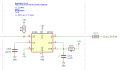
It is helpful to easily see the activity on the CAN bus.
Presently, I have an LED on TX and RX, however, they just barely flicker due to the speed and short duration (200 micro-seconds).
While a 555 solution works to lengthen the ON time of the LEDs, it is not elegantly simple, many parts.
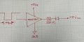
I would have expected a simple capacitor to do the job.
Tried many capacitors, and configurations, no real progress, perhaps due to limited options in-stock here )
So hoping there is a CAPACITOR EXPERT visiting this site )
 

Attachments

ElectricSpidey

Joined Dec 2, 2017
3,312
Connecting the circuit in post #2 to the output of the buffer in the OP will require a pullup resistor.

EDIT:
Looking at the circuit in the OP again I see that it is a 200us "negative" signal that must be extended. In that case the circuit in post #2 should be a PNP type instead of a NPN type, and therefore no pull resistor or diode is needed.

The cap will charge when the output of the buffer is low and will not discharge thru the buffer because it is open drain.
 
Last edited:

MrChips

Joined Oct 2, 2009
34,629
Thank you kindly for the reply, but this circuit does not hold my LED ON longer. Actually, my LED will not come ON with this circuit, since my negative pulse (active LOW) is so narrow. Yes I tried with an active HIGH as well. The pulse width must be 20 milliseconds wide to come ON here.
To be honest, I never tested this circuit. I think that there is still a reasonably simple solution.
Use two monostable multivibrators, using LMC555, CD4098, MC14528, or MC14538 to generate longer pulses from an input trigger. You can use retriggerable or non-retriggerable monostable depending on the desired effect.
 

MrChips

Joined Oct 2, 2009
34,629
You could try my original circuit but add a pull-up and pull-down resistor at the base to just bias the transistor just before turning on.

(We need to know if the signal to be monitored, after being buffered, is low or high while in the idle state.)
 

Beau Schwabe

Joined Nov 7, 2019
186
Altering MrChips original circuit might work ...

Changing the NPN to a PNP and placing the Capacitor on the collector side of the transistor and changing a few resistor values.

Note1: The transistor will experience very brief pulses that about 450mA
Note2: To create the 200us pulse I have an oscillator running at 100 Hz with a 98% duty cycle

Simulation:
https://tinyurl.com/2fnnswo7
 
Top