 Facebook
 Google
 GitHub
 Linkedin
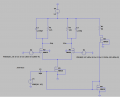
Here's the problem:

So i already tried to size the circuit and here's what i got:

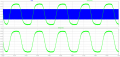
Here is the IF signal and RF signal:

I think the IF signal is a bit distorted but overall it's ok.
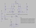
To bias the circuit i used a current mirror and 3 voltage dividers, is it ok if i do the biasing like that?
Also to compute the mixer noise, should i take into account the biasing circuit?
In razavi book i can compute the total output noise without the biasing and the 2 capacitors in parallel with RL:

But perhaps it's better to compute it using LTSpice or some other program (because doing it analytically taking into account the biasing circuit seems like a nightmare)?
Also i would like to add that if i drop the input signal amplitude below 0.4V the IF signal goes to 0.... Why does that happen?
So i already tried to size the circuit and here's what i got:
Here is the IF signal and RF signal:
I think the IF signal is a bit distorted but overall it's ok.
To bias the circuit i used a current mirror and 3 voltage dividers, is it ok if i do the biasing like that?
Also to compute the mixer noise, should i take into account the biasing circuit?
In razavi book i can compute the total output noise without the biasing and the 2 capacitors in parallel with RL:
But perhaps it's better to compute it using LTSpice or some other program (because doing it analytically taking into account the biasing circuit seems like a nightmare)?
Also i would like to add that if i drop the input signal amplitude below 0.4V the IF signal goes to 0.... Why does that happen?
Attachments
-
 23.1 KB Views: 3
 -
 52.8 KB Views: 1
 -
 67.4 KB Views: 0
Last edited:


