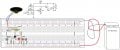
It looks like that the collector and emittor of Q1b are the wrong way around.
You have the emittor to ground in stead of the collector.
The collector is connected to R3, but not to the base of Q2.
I tried the original @Wendy circuit with a BC547 and a BC557. It works! Now to add another BC557 to make the Sziklai pair and see what difference it makes. I only found out about Sziklai pairs after joining this forum.
I tried the original @Wendy circuit with a BC547 and a BC557. It works! Now to add another BC557 to make the Sziklai pair and see what difference it makes. I only found out about Sziklai pairs after joining this forum.
I have a whole lot of BC557/547 from some items that I took apart awhile back. Probably an old printer or fax machine. I use these for experimenting with stuff. I have a treasure trove of parts from things like that.
Ok, after much collector emitter confusion, I got the Sziklai version of this little siren to work. Much louder than the single transistor version. Fun little project. But my cat did not like it, he left the room. Thanks, @Wendy .
I finally got this son of a gun to work, it appears it was a gain issue. Just wish I understood the oscillator better. I will post the schematic on the next post so I can write it up for my protoboard cookbook thread
This is a cute little siren circuit could I found when i was under 18 in a RadioShack 75 in 1 toy. I never did understand why Q1 was so critical, the original circuit used a germanium transistor. I suspected it might have been a gain issue so I substituted Q1 with a Sziklai pair to increase the gain which worked. The original design cycled up the frequency a little bit better reminding me of the old-fashioned sirens the police forces used to use. This shows that the circuit has an element of VCO which helps the sound. The Sziklai pair increases the complexity more than I like but I am not going to spend over $10 for germanium transistor. Press the button to create a siren sound.
 Facebook
 Google
 GitHub
 Linkedin