This circuit uses a single hex inverter chip to create two monostables with inputs that have extra added hysteresis, and are terminated and current limited for transient protection. Also, the output pulses are the correct polarity.
And for a debouncer, a guaranteed minimum pulse width is needed, one whose length is known to be longer than the worst case bounce period. A pulse stretcher can not guarantee this. Again, to get an output that has a constant pulse width whether the input pulse is shorter, longer, or the same length you must have something in the circuit that takes over once the initial edge happens, making the finishing of the pulse completely independent of the input. That takes feedback and control - positive feedback and an AND/OR function of some flavor.
Take a look at the OP's request. Your circuit assumed an active low input (key presses produced logic 0s), vs. an active high input (key presses produced logic 1s)
Take a look at the OP's request. Your circuit assumed an active low input (key presses produced logic 0s), vs. an active high input (key presses produced logic 1s)
True, but the schematic he posted made it clear that the input level assignment was completely arbitrary. That's why I flagged the switch action on the schematic.
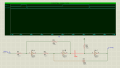
The one I posted earlier is edge triggered: continued high level of input signal has no effect on the circuits, once triggered. The simulation showed as much.
For the circuit in post #37, the output stays high as long as the input stays high, so the two are not independent. In fact, no matter how short the input pulse is, down to the point that the circuit doesn't function, the output pulse width always is influenced by the width of the input pulse.
For the circuit in post #39, the output pulse width is a combination of two R-C time constants plus other factors. The input signal must stay high longer than the first time constant or it will terminate the U1A output pulse early. And as mentioned before, the second RC stage is directly influenced by the amount of time the capacitor is discharged through D1, which is controlled by the U1A output.
One way to gauge true input-to-output independence is to crank up the speed. If the input pulse were 100 nanoseconds wide, could button2 produce an accurate 1 second output pulse? What if the gates were Shottkey TTL (with appropriate adjustments to R2 and C2) and the input signal were 25 ns wide?
First let me be clear here. None of these circuits are "bad" or "wrong". They all work well within certain parameters, and in fact I've used all of them over the years and in posts in other threads here. But if we are drilling down into the subtleties of the requirement is for an output pulse that is completely independent of the input (after the first actuating edge), nothing without feedback will work across the entire ranges of devices and speeds.
As for the circuit in post #23, the output pulse is terminated early by releasing the switch. Also, if the contact bounce burst is timed right it will show up on the output to the counter. The 40106 has 20% hysteresis (worst case) which reduces the possibility of this, but does not completely eliminate it like the 100% positive feedback of a classic two-NAND or two-NOR monostable.
Also, it increments the counter on the trailing edge of the output pulse and leaves the timer in a non-recommended state between pulses.
First let me be clear here. None of these circuits are "bad" or "wrong". They all work well within certain parameters, and in fact I've used all of them over the years and in posts in other threads here. But if we are drilling down into the subtleties of the requirement is for an output pulse that is completely independent of the input (after the first actuating edge), nothing without feedback will work across the entire ranges of devices and speeds.
The user doesn't have control over the duration of the pulse and its easy to lengthen the pulse duration is needed. Please explain what you mean by "terminated early by releasing" the switch?
show up on the output to the counter. The 40106 has 20% hysteresis (worst case) which reduces the possibility of this, but does not completely eliminate it like the 100% positive feedback of a classic two-NAND or two-NOR monostable.
#I am gonna connect it to DOWN pin in 74LS192 Up/Down counter. pulse should be enough to activate the DOWN pin (maybe 100ms or less) and must be HIGH all the time.
The reason why I need this is because if the DOWN pin stays at LOW, when I activate UP pin, it counts double or triple. It is when I press and hold the push button, giving LOW to DOWN pin, then count UP, it messed up until I release the DOWN push button.
My outputs are Clean when I tested them.
555 monostable doesn't seem to work on what I need. I don't know if I did something wrong.
note:
My time and resources are limited. Logic ICs, 555, Caps, Resistors, and 2N2222 Transistors, and I think it's enough. I can buy or Order some components if needed, but it takes time to arrive, so.. meh.
I am actually making a Coin counter for our project. and I want to avoid multiple counts on a single coin when the Start button (down count) is being depressed.
Keep the questions coming. And I'm not sure it got more complicated, just better defined.
Looking at the UP half of the circuit in post #23, things start out with C1 discharged; both ends are at GND and U1 out is high. When S1 closes, the left side of C1 is yanked up to Vcc, crossing U1's input transition region and causing the inverter to change state, and U1 out goes low. The right side follows, and then starts to move back toward GND as C1 charges up. Eventually it crosses U1's transition region in the other direction and the output returns high.
But, if the UP switch is opened before C1 has charged up, and U1 out still is low, R2 pulls the left side of C1 back to GND, yanking the right side of C1 below GND, forcing U1 out high immediately. This is how switch bounce can directly affect the width of the output pulse, and even introduce noise into it if the planets are aligned.
Think about that for a second. For any circuit, yours include, there always exists a sufficiently short pulse that the circuit will not respond too. So it seems pointless to use that as a yard stick.
Not to mention that the opposite of it is desirable here. You don't want the circuit to respond to too short pulses.
uhhm. Guys, the pulse length doesn't need to be too short, it can be 500ms, as long as it is enough to count up, but short enough that the UP count trigger won't meet with the pulse.
again, the Up counter is connected to coin counter (it's the one where you drop your coins in the arcade) with digital 0 and 1 output followed by Schmitt trigger as debouncer.
then the pulse is for the down counter.
Thanks again. will test those new schematics tonight!
Think about that for a second. For any circuit, yours include, there always exists a sufficiently short pulse that the circuit will not respond too. So it seems pointless to use that as a yard stick.
Again sticking with the boxcar circuit in post #23...
The reason I mentioned specific time delays was to avoid having this thread get bogged down in distractions. Of course there is a minimum input pulse width that can defeat any timing circuit. But analyzing the maximum possible performance is one way to differentiate two circuits that might appear similar in one situation, but in fact have a performance sensitivity that is over 1000:1 different between the two.
My point is that for a true monostable that pulse width is limited by the propagation delays of the active components , usually down in the nanosecond range, and is almost completely independent of the performance of the passive components, especially the capacitor. A simple differentiator or boxcar circuit is critically dependent on the high frequency performance of the capacitor, the value of the timing resistor compared to the input current of the gate following it, and especially the timing of the input pulse. It's not just that these factors affect the width of the pulse formed by the incoming edge, it's that these factors can prevent that pulse being formed at all. For all practical purposes, a monostable with logic feedback is immune to all of these effects, especially the timing of the input pulse.
 Facebook
 Google
 GitHub
 Linkedin
")


