Single phase 2 winding transformer

Thread Starter

mjb1972

Joined Sep 18, 2016
5
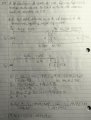
The information given is N1=2000, N2=500, winding resistances: RN1=8ohms, RN2=0.125ohms, leakage reactances: XN1=8ohms, XN2=0.5ohms, resistance load on secondary = 12ohms.
If Vp=1000V, determine V2 @ the load terminals of the transformer, neglecting magnetizing current.

I know that the resistances and reactances are to be placed in series on their respective sides of the transformer, but I'm not sure about the excitation branch since Ie = Ic + Im. If I am only to neglect Im, do I neglect the entire excitation branch?
I have set up the problem as:
upload_2016-10-1_10-24-56.png
PS: Homework is not collected. It is only assigned to prepare for exam Thursday Oct. 6th

Thank you for any guidance.
 

MrAl

Joined Jun 17, 2014
11,486
Hi,

I have trouble reading your diagrams because they are so dark and, well, hard to read. I might try to clean them up later, but here is some general advice.

First, the resistances and reactances add vectorially not directly.
Second, you can reflect everything on the secondary to the primary, and that often simplifies the problem.
Third, the reflection of stuff on the secondary translates by a factor equal to the square of the inverse turns ratio. Since the ratio looks like 4:1, that means that going in reverse it is 1:4 and squaring that it is 1:16 so any resistance on the secondary gets multiplied by 16. So 1 ohm on the secondary side in series equals 16 ohms on the primary side in series. Once you get everything reflected to the primary, you no longer have a transformer, just a plain passive circuit with an inductor and a resistor. You can then calculate the primary current, and using the turns ratio you can calculate the secondary current (with the reverse tuirns ratio again).
There are other ways to do this but see if that helps.

See if this new image helps...
 

Attachments

Last edited:

Thread Starter

mjb1972

Joined Sep 18, 2016
5
That just seems like a lot of current, especially since a transformer
Hi,

I have trouble reading your diagrams because they are so dark and, well, hard to read. I might try to clean them up later, but here is some general advice.

First, the resistances and reactances add vectorially not directly.
Second, you can reflect everything on the secondary to the primary, and that often simplifies the problem.
Third, the reflection of stuff on the secondary translates by a factor equal to the square of the inverse turns ratio. Since the ratio looks like 4:1, that means that going in reverse it is 1:4 and squaring that it is 1:16 so any resistance on the secondary gets multiplied by 16. So 1 ohm on the secondary side in series equals 16 ohms on the primary side in series. Once you get everything reflected to the primary, you no longer have a transformer, just a plain passive circuit with an inductor and a resistor. You can then calculate the primary current, and using the turns ratio you can calculate the secondary current (with the reverse tuirns ratio again).
There are other ways to do this but see if that helps.

See if this new image helps...
It's strange it looks dark. I can see it but that doesn't matter. I have reflected the secondary resistances and leakage reactances to the primary by multiplying each by the square of the turns ratio. I did not, however reflect the load resistance. If I'm understanding you correctly, I should reflect the load to the primary as well and solve for the current in the primary as if it were a basic RL circuit. Then this current can be reflected back to the secondary at which time I can solve for the output voltage. Is this correct? Thank you for you advice. Unfortunately, this book doesn't provide answers to the odd numbered problems like many others do. So, even if I were to solve in a manner I believe to be correct, I will have no way of knowing if I actually am. Thank you again for your advice. I will continue with the problem and bring questions to the professor Monday.
 

MrAl

Joined Jun 17, 2014
11,486
That just seems like a lot of current, especially since a transformer

It's strange it looks dark. I can see it but that doesn't matter. I have reflected the secondary resistances and leakage reactances to the primary by multiplying each by the square of the turns ratio. I did not, however reflect the load resistance. If I'm understanding you correctly, I should reflect the load to the primary as well and solve for the current in the primary as if it were a basic RL circuit. Then this current can be reflected back to the secondary at which time I can solve for the output voltage. Is this correct? Thank you for you advice. Unfortunately, this book doesn't provide answers to the odd numbered problems like many others do. So, even if I were to solve in a manner I believe to be correct, I will have no way of knowing if I actually am. Thank you again for your advice. I will continue with the problem and bring questions to the professor Monday.
Hi again,

Yes, that sounds right, and once you have the current and multiply by the turns radio you know the actual output voltage because you know both the current and the load.

Here's a quick example which may or may not be a real life example but works in theory...

Specification:
Tranformer with 10:1 turns ratio, 1 ohm primary winding resistance 0.01 ohm secondary winding resistance.
Input: 11v
Expected output voltage very roughly around 1v because of the 10:1 turns ratio.
Output load: 0.09 ohms.
Goal: To calculate output current and output voltage across the load.

First we have the total output resistance is 0.01+0.09=0.1 ohms.
Reflecting that back to the primary, we have R=10^2*0.1=10 ohms.
The primary already has 1 ohm, so now we have a total of 1+10=11 ohms.
The input is 11 volts, and 11/11=1 amp primary current.
The secondary current must follow the turns ratio, so the secondary current is 1*10=10 amps.
The secondary current flows through the load, and the load is 0.09 ohms, so the output voltage is 0.09*10=0.9 volts.
As you can see this example was manufactured to have nice roundish numbers :)

That's the easiest way to do this i think. There are other ways though such as the use of dependent sources but i think that is more complicated. Of course there is also the two port network view.

BTW you can use a simulator to check some of your results. A free simulator that many people here use is the LT Spice simulator, i think it is called Switchercad.
 

Thread Starter

mjb1972

Joined Sep 18, 2016
5
Hi again,

Yes, that sounds right, and once you have the current and multiply by the turns radio you know the actual output voltage because you know both the current and the load.

Here's a quick example which may or may not be a real life example but works in theory...

Specification:
Tranformer with 10:1 turns ratio, 1 ohm primary winding resistance 0.01 ohm secondary winding resistance.
Input: 11v
Expected output voltage very roughly around 1v because of the 10:1 turns ratio.
Output load: 0.09 ohms.
Goal: To calculate output current and output voltage across the load.

First we have the total output resistance is 0.01+0.09=0.1 ohms.
Reflecting that back to the primary, we have R=10^2*0.1=10 ohms.
The primary already has 1 ohm, so now we have a total of 1+10=11 ohms.
The input is 11 volts, and 11/11=1 amp primary current.
The secondary current must follow the turns ratio, so the secondary current is 1*10=10 amps.
The secondary current flows through the load, and the load is 0.09 ohms, so the output voltage is 0.09*10=0.9 volts.
As you can see this example was manufactured to have nice roundish numbers :)

That's the easiest way to do this i think. There are other ways though such as the use of dependent sources but i think that is more complicated. Of course there is also the two port network view.

BTW you can use a simulator to check some of your results. A free simulator that many people here use is the LT Spice simulator, i think it is called Switchercad.
Thanks again. I have used your advice to finish the problem. I also compared it to in class examples, even if they are not exactly the same and feel confident of the result. I found the primary current with all resistances, reactances, and the load reflected to primary. I used the turns ratio, and the knowledge that a step down transformer has high voltage and low current on the primary and low voltage and high current on the secondary, to come to a solution that seems to make sense. Just for kicks I multiplied the current in the secondary by the load to see if the voltage drop across the load matched. It was close but not exact. I would like to thank you for your time and patience in helping me with this problem. Here is a picture of my result. Hopefully you can see it a bit better. I tried to lighten it a little.
upload_2016-10-2_14-29-57.png
I used voltage divider to obtain E1 then the turns ratio (a) to find E2. I hope its a bit more clear. Thank you again for the push in the right direction.
 

MrAl

Joined Jun 17, 2014
11,486
Hi there,

I will try to enhance that drawing and see if it gets more readable.

In the mean time, here is another example complete with input series inductance and output series inductance, and keep in mind we are assuming perfect coupling so there is an ideal transformer between those two inductances. I think that is what you are after, but we can always look at a mutual inductance case later too.

This next example has all the same properties of the first example, with the following additions:
1. 1mH inductor in series with the secondary resistance.
2. 10mH inductor in series with the primary resistance.
3. The 11vac input source is at a frequency of 100Hz.

Note these two are just arbitrary thrown at the problem in order to create an example with the two inductances present in addition to the primary and secondary resistances. In many cases we have to think about the mutual inductance too, but here we dont.

So given that everything is the same as before except for those two inductors, and the input is still 11v, the output voltage comes out to a complex quantity:
Vout=9.9/(22*i*pi+11)
and converted into real and imag parts:
Vout=108.9/(484.0*pi^2+121)-(217.8*i*pi)/(484.0*pi^2+121)
or in floating point:
Vout=0.02223407072867-0.1397007865212*i
and computing the amplitude i get:
0.14146
and in simulation as best as i can tell after zooming in i get:
0.14147

These two results are close enough for me :)

Oh BTW you may be interested in calculating the phase shift also, if you havent done that yet.

I'll see if i can read your paper and check it over.
 

MrAl

Joined Jun 17, 2014
11,486
Hello again,

(see first post above first, #6)

Ok i think i was able to follow your paper.
If so, then i get an output voltage that is equal to your E2 in the paper.
That's about 244.09vac and angle of about -4.67 approx.

So see if that matches what you got, because i wasnt quite sure what you were doing after that.
Maybe calculating the secondary output before any reactance or winding resistance? Not sure there, but you can do that although not sure why you would want to do that as i thought you wanted the output voltage across the load of 12 ohms.
 

Attachments

Thread Starter

mjb1972

Joined Sep 18, 2016
5
Hello again,

(see first post above first, #6)

Ok i think i was able to follow your paper.
If so, then i get an output voltage that is equal to your E2 in the paper.
That's about 244.09vac and angle of about -4.67 approx.

So see if that matches what you got, because i wasnt quite sure what you were doing after that.
Maybe calculating the secondary output before any reactance or winding resistance? Not sure there, but you can do that although not sure why you would want to do that as i thought you wanted the output voltage across the load of 12 ohms.
I needed to refer it back to its original location. I think I needed to do that. When I put it back I needed to do a voltage divider to get the actual voltage across the load.
 

MrAl

Joined Jun 17, 2014
11,486
I needed to refer it back to its original location. I think I needed to do that. When I put it back I needed to do a voltage divider to get the actual voltage across the load.
Hi,

Not sure what you mean there.

What i meant was that in your paper where you show E2=244.09v, that is actually V2 not E2 in the drawing of the transformer and load. In other words, i got 244.09v as the output right across the 12 ohm load, period.
That's why i dont understand why you did that extra work, unless you needed to know the voltage at the secondary of the ideal transformer (before the secondary resistance and secondary inductance).

Once you calculate the primary current and then the secondary current Is the output voltage is then just:
Vout=Is*RL

and that is because everything in the secondary is in series and the current is the same through every element in a series circuit. So if you want the voltage across any element in the secondary circuit you just multiply the current times it's impedance:
V=Is*Z

where Z is the impedance of the element. Since the output load is 12 ohms non reactive the output voltage is Is*12, but if you wanted the voltage across ALL three elements of the secondary only then you would need to do:
Is*(Z1+Z2+Z3)=Is*(Rs+jwL+RL)

but that is a voltage internal to the transformer because that appears across the secondary of the ideal transformer which we never have access to directly.
 
Top