simulation of the behaviour of a PCB Spark Gap

Bordodynov

Joined May 20, 2015
3,431
Yes, I knew that, but still, I'm not able to understeand the pictures at all, maybe because I don't know what those parameters mean (for example Ron, R0..) Also, I don't know where you modify the gap distance between the electrodes.
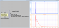
In my model there is no such parameter as the distance between the electrodes. The parameter is the breakdown voltage of the arrester in the static mode vb_min. This parameter you calculate. LTspice allows you to calculate any parameter using the formula. For example: .param P=1 d =0.1 vb_min=3000*P*d+1350.
The remaining parameters are adjustable, they have no direct physical meaning. I just selected these parameters, in order to get the arrester parameters as in the datasheet.
By the way, I'm not sure about your formula.
 

Thread Starter

marc1996

Joined Aug 1, 2018
18
In my model there is no such parameter as the distance between the electrodes. The parameter is the breakdown voltage of the arrester in the static mode vb_min. This parameter you calculate. LTspice allows you to calculate any parameter using the formula. For example: .param P=1 d =0.1 vb_min=3000*P*d+1350.
The remaining parameters are adjustable, they have no direct physical meaning. I just selected these parameters, in order to get the arrester parameters as in the datasheet.
By the way, I'm not sure about your formula.
That's the most accepted formula but, ofcourse is not that accurate.

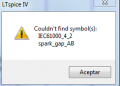
Where can i found your spark gap model? I can find this symbol in my libraries.

Thanks!!
 

Bordodynov

Joined May 20, 2015
3,431
and what about connecting the @Bordodynov spark gap into the ESD output of the IEC simulator? then the current will go through the spark and depending of the breakdown voltage that we assigned we will get some different results, or am I wrong?

edit:
I found an spark gap simulator here:
http://ltwiki.org/?title=Adventures_with_Analog

I have an improved arrester model. What you found was a prototype for me.
I made an improved model IEC61000_4_2 for LTspice. You can download my models here:
https://forum.allaboutcircuits.com/...nents-models-of-ltspice-free-download.133690/


looks like the one that @Bordodynov has but it got a lot of text that I don't know what is tbh..
 

ebp

Joined Feb 8, 2018
2,332
I often say that if you use a model for a horse, don't expect it to give you good results if you want to simulate a cow.

I haven't looked at the video, but the still image that appears on my screen is the spark gap. I see several things that are likely to have significant effect.
  • There is not a single, well-defined gap but multiple gaps. This will influence pre-spark ionization that relates to what Bordodynov is trying to show you. The voltage gradient between the two sides becomes diffuse.
  • There is solder mask surrounding the gaps, with what looks like zero clearance between the foil and the mask aperture. This makes consistency nearly impossible and would be very detrimental to experimental results. If the tips of the points are covered with solder mask they are effectively insulated to quite high potential. Spark-over is now likely to be surface-to-surface rather than point-to-point, and I would expect that would result in substantially higher spark-over voltage.
  • There is a big blob of solder on the foil. This will probably change the geometry of the points enough for at least some change in properties.
  • Worst of all, there is clearly solder flux all over the place. The base material of flux is generally a good insulator. The activators are ionic. It wouldn't surprise me if the flux caused spark-over voltage variation of 2 to 1 or more.
No model that omits the influence of these things will give you any sort of worthwhile answer. Building a model that incorporates these things requires a lot of empirical work and careful data collection and analysis. Data and analysis first - model when you've learned enough to tell a cow from a horse.
 

Thread Starter

marc1996

Joined Aug 1, 2018
18
I often say that if you use a model for a horse, don't expect it to give you good results if you want to simulate a cow.

I haven't looked at the video, but the still image that appears on my screen is the spark gap. I see several things that are likely to have significant effect.
  • There is not a single, well-defined gap but multiple gaps. This will influence pre-spark ionization that relates to what Bordodynov is trying to show you. The voltage gradient between the two sides becomes diffuse.
  • There is solder mask surrounding the gaps, with what looks like zero clearance between the foil and the mask aperture. This makes consistency nearly impossible and would be very detrimental to experimental results. If the tips of the points are covered with solder mask they are effectively insulated to quite high potential. Spark-over is now likely to be surface-to-surface rather than point-to-point, and I would expect that would result in substantially higher spark-over voltage.
  • There is a big blob of solder on the foil. This will probably change the geometry of the points enough for at least some change in properties.
  • Worst of all, there is clearly solder flux all over the place. The base material of flux is generally a good insulator. The activators are ionic. It wouldn't surprise me if the flux caused spark-over voltage variation of 2 to 1 or more.
No model that omits the influence of these things will give you any sort of worthwhile answer. Building a model that incorporates these things requires a lot of empirical work and careful data collection and analysis. Data and analysis first - model when you've learned enough to tell a cow from a horse.
Thank you for your time ebp.
I knew some of the info that you wrote there. I have read a lot of times that the gap should be clean of solder mask, if not will be really really hard that the spark occurs.

Anyway, if I find a way to simulate the pcb spark gap in a "decent real conditions", I will let you know in case someone is interested.
Thanks!
 

Thread Starter

marc1996

Joined Aug 1, 2018
18
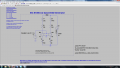
upload_2018-8-3_11-18-57.png

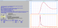
That's my circuit right now. I have been trying different gap distances but seems that the value of the current/voltage is not changing, the only thing that is changing when i change the parameter "d" is the time needed to start the overshoot of current. I mean for example, with d = 0.3 maybe the peak current is at 80ns while with d = 0.9 is at 500 ns, but the max value of the current is still the same.

btw, what is the meaning of the tau and the Vexp parameters? I don't know if I should modify them or why they got those values..
 
Last edited:

Bordodynov

Joined May 20, 2015
3,431
At the top of the diagram, I put the model text. In the initial model of the arrester from analogspiceman, to simulate the initial ionization current, there was simply a resistor, which I did not like, because current goes even at low voltages. I made the exponential dependence of this current on the voltage. The development of breakdown can not occur immediately. So I added a time constant Tau. All this allowed me to simulate real arresters. The formula for the discharge voltage is not right for you. I made an approximation for the case where one electrode is flat. Really, I think the breakdown is less. I advise you to measure the breakdown experimentally.
 

Alec_t

Joined Sep 17, 2013
15,149
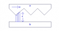
It occurs to me you might be able to take electrode shape into account by simulating a gap as an array of micro-gaps, like this :-
ShapedGap.PNG
Each blue rectangle represents a separate exemplary micro-gap, which could be modelled using Bordodynov's model.
If d is a known function of x the array could be defined mathematically.
The application of voltage to the individual gaps could be simulated by treating electrodes a and b as a non-uniform transmission line; but there the maths get a tad involved :) .
 

Thread Starter

marc1996

Joined Aug 1, 2018
18
At the top of the diagram, I put the model text. In the initial model of the arrester from analogspiceman, to simulate the initial ionization current, there was simply a resistor, which I did not like, because current goes even at low voltages. I made the exponential dependence of this current on the voltage. The development of breakdown can not occur immediately. So I added a time constant Tau. All this allowed me to simulate real arresters. The formula for the discharge voltage is not right for you. I made an approximation for the case where one electrode is flat. Really, I think the breakdown is less. I advise you to measure the breakdown experimentally.
Sorry for my delay answering you.
Thanks for your answer. I read this link like 1 month ago. What you explained to me looks really complex for me to understeand because I do not know much about LTspice so, I don't know at all how you configured all of this.

I will try to keep improving my skill with this software in order to understeand more what the different things that appear in the circuit are.

It occurs to me you might be able to take electrode shape into account by simulating a gap as an array of micro-gaps, like this :-
View attachment 157471
Each blue rectangle represents a separate exemplary micro-gap, which could be modelled using Bordodynov's model.
If d is a known function of x the array could be defined mathematically.
The application of voltage to the individual gaps could be simulated by treating electrodes a and b as a non-uniform transmission line; but there the maths get a tad involved :) .
Sorry for my delay.
Do you mean simulating different distances between gaps in order to make the shape form with the d value? So I would know depending on the voltage where the spark will jump. Thats what you mean?
 

Alec_t

Joined Sep 17, 2013
15,149
Do you mean simulating different distances between gaps in order to make the shape form with the d value?
Yes. A sequence of d values. But I still think the spark would jump the shortest gap, hence electrode shape either side of that would be largely irrelevant, other than, perhaps, to compensate for electrode erosion by the spark and provide 'back-up' gaps for handling successive sparks.
 

Thread Starter

marc1996

Joined Aug 1, 2018
18
Yes. A sequence of d values. But I still think the spark would jump the shortest gap, hence electrode shape either side of that would be largely irrelevant, other than, perhaps, to compensate for electrode erosion by the spark and provide 'back-up' gaps for handling successive sparks.
Yes, I think the same. in your scheme, imo they would jump in the 3 sharps, in a random way. Maybe it jumps in the middle one and then change to the left one or, maybe, it starts in the right one and there is no more jumps.. As far as I know, there is no theoric way to know where the spark will occurs if the 3 edges are at the same distance from the other electrode.
 

Thread Starter

marc1996

Joined Aug 1, 2018
18
update: I'm trying to do it now using CST MWS. I'm learning how to use the program but I think I will get better results using a FEM software. My SPICE circuit wasn't doing what was supposed to do when i was changing the distance value between electrodes..
 
Top