Simulating magneto primary signal.

Thread Starter

GasTech

Joined Nov 27, 2024
6
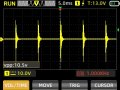
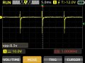
I need help designing a circuit that would emulate the signal generated by a magneto's primary. I need this to repair and verify the functionality of generator controls that use this signal to measure the engine's RPM. The signal is a negative pulse in the order of -300 vdc which is displayed below. The scope probe was set to 10X and the generator this sample was taken from is a twin cylinder thus the signals being in pairs. There's 240VAC and 12VDC available to design the circuit and I will need to be able to change the frequency of those pulses to simulate a change in RPM and analyze the reaction from the controller. I have seen some circuits with a square wave as starting point to get negative pulses but I need suggestions to reach the high negative voltage.
Coiljpg.jpg
 

crutschow

Joined Mar 14, 2008
38,322
What is the input impedance of the controller?
What frequency (RPM) range do you need?

One way is to use a flyback circuit.
For example, an 10:1 flyback transformer would give a 300V output pulse, for a 30V flyback voltage on the primary.
 

crutschow

Joined Mar 14, 2008
38,322
Below is the LTspice sim of an example flyback circuit using a 555 pulse generator with a 10:1 turns-ratio pulse transformer to generate the negative pulse:
The output pulse (red trace) is ≈-400V with a 200pF stray capacitance load.

D1 limits the primary voltage spike to below the MOSFET's rating
C1 and R3 damp out the ringing after the pulse.
Pot U2 adjusts the pulse frequency (here set to about 1kHz, emulating 2000 RPM for a 4-stroke single-cylinder engine).

Is that about what you wanted?

1732920216379.png
 
Last edited:

MisterBill2

Joined Jan 23, 2018
27,186
Can the TS supply a picture of the cope trace at a sweep rate fast enough to let us see what the spike actually is shaped like???In reality it must have some width, and the width will help understand the power that must be provided. A fast one-shot can set the width in a stable and predictable manner.
 

Thread Starter

GasTech

Joined Nov 27, 2024
6
That is pretty much what I was looking for, thank you Crutchow, I'll be using a small PWM to generate the square wave instead of a 555 and found an old ignition coil I can use for the transformer. Using a proper ignition coil should provide an acceptable signal to the controller. Although not very elegant, I will accept a bit of Frankentronics to my test bench for now.
I am very impressed with all the help and knowledge here and will report here when done. Cheers.
 

crutschow

Joined Mar 14, 2008
38,322
found an old ignition coil I can use for the transformer
Ignition coils typically have about a 100:1 turns ratio, so the primary pulse needs to be 3V for a 300V output, provided the output load is a high impedance.

Below is my circuit modified to use the ignition coil:

1733061954411.png
 
Last edited:

Thread Starter

GasTech

Joined Nov 27, 2024
6
Thanks for the update, tapping the primary, I'm expecting a voltage of 300-400 volts. I just downloaded LTspice powerful software! I've looked at a similar circuit from Reloadron to drive an ignition coil, some components are missing but it's similar to your solution. I'll ramp up the voltage gradually and see what I get out of the primary. Cheers!
 

Thread Starter

GasTech

Joined Nov 27, 2024
6
Ignition coils typically have about a 100:1 turns ratio, so the primary pulse needs to be 3V for a 300V output, provided the output load is a high impedance.

Below is my circuit modified to use the ignition coil:

View attachment 337101
I managed to have a signal close to what I think would work but the output flattens when I put diode D4 in the circuit. Instead of a 555, I'm using a small pwm circuit with a display to produce the pulses, C1 seems to block the signal as is so it isn't in the circuit. I assume there is an impedance mismatch causing the signal to flatten to noting and that probably wouldn't happen hooked up to a controller but would like to take the positive side of the output out before proceeding. The screenshot below is taken at the output of the secondary of the ignition coil. The signal is pretty rough and goes through a Schmitt Trigger IC within the controller. Many thanks for your help.
Ignition coils typically have about a 100:1 turns ratio, so the primary pulse needs to be 3V for a 300V output, provided the output load is a high impedance.

Below is my circuit modified to use the ignition coil:

View attachment 337101
Ignition coils typically have about a 100:1 turns ratio, so the primary pulse needs to be 3V for a 300V output, provided the output load is a high impedance.

Below is my circuit modified to use the ignition coil:

View attachment 337101
I manage to get pretty much what I think will be accepted by the controller, however, the signal from the secondary of that ignition coil collapses as soon as I use D4 to get rid of the positive part. I think the impedance of the controllers is high enough for this not to happen but would like to get rid of the positive part of the signal before hooking it up to a good unit. I wasn't getting voltage to L2 with C1 in the circuit so I took it out. I'm also using a small PWM circuit with a display instead of a 555, I can easily see the frequency and duty %on it. Thank you for your help.
 

Attachments

MisterBill2

Joined Jan 23, 2018
27,186
Keep in mind that engine speeds are revolutions per MINUTE, while the frequencies are CYCLES per SECOND.
And with a 4-stroke firing every other cycle, it is half that ., although a single cylinder magneto ignition engine will spark on every revolution. both compression stroke and exhaust stroke.
 

Thread Starter

GasTech

Joined Nov 27, 2024
6
I had success today simulating a single cylinder at 60 hertz despite a positive voltage trace present, the signal is attached. The output of the coil goes through a diode (BY500-100) blocking the positive part but for some reason some of it is still there. Could it be capacitive effect from the breadboard or bad choice of diode? With low frequency I didn't think that would be an issue at this stage. How can I filter this out properly? I'll try to post a proper schematic soon. Cheers.
 

Attachments

Thread Starter

GasTech

Joined Nov 27, 2024
6
That screen grab was done with the controller hooked up and the scope probe at 10x. I'm thinking it's coming from the breadboard, I'll update to a small board soon and see what effect it has. In any case it works now, so I can move forward. Very thankful for your help.
 
Top