Facebook
 Google
 GitHub
 Linkedin
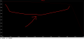
Hello,I want to test the PNP BIASING of my regulator I get only 2mA from the PNP Ic.
Is there a way to simulate a fluctuating load so I could see how well the regulator works?
Thanks.
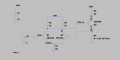
LTspice file is attached.
https://www.onsemi.com/pdf/datasheet/2n3906-d.pdf


Is there a way to simulate a fluctuating load so I could see how well the regulator works?
Thanks.
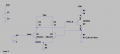
LTspice file is attached.
https://www.onsemi.com/pdf/datasheet/2n3906-d.pdf
Attachments
-
1.6 KB Views: 1