Facebook
 Google
 GitHub
 Linkedin
Dear All
I am coming to you regarding the possibility to use JFETs as a variable resistor.
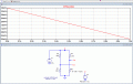
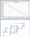
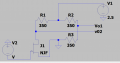
I am trying to simulate a JFET to vary between the resistance 348ohm to 350ohm. So as to simulate a quarter bridge wheatstone circuit over 350ohm as shown in the attached image.
I am trying to unbalance the bridge to simulate an output by change the resistance of the JFET branch between 348ohm to 350ohm. But i am a bit lost on how to proceed. Could you please help
Thanks in advance,
I am coming to you regarding the possibility to use JFETs as a variable resistor.
I am trying to simulate a JFET to vary between the resistance 348ohm to 350ohm. So as to simulate a quarter bridge wheatstone circuit over 350ohm as shown in the attached image.
I am trying to unbalance the bridge to simulate an output by change the resistance of the JFET branch between 348ohm to 350ohm. But i am a bit lost on how to proceed. Could you please help
Thanks in advance,
Attachments
-
 37.1 KB Views: 25
")