Simulating a generator in LTSpice

Thread Starter

cmartinez

Joined Jan 17, 2007
8,252
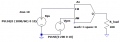
How would one go around simulating a generator in LTSpice? Its output waveform would be sinusoidal.

Say, I'd like to sim the fact that as the revs go up, so does the power generated, it's voltage and its frequency. And when it stops, it'd behave like a short circuit.

The generator type would be variable reluctance.
 

Thread Starter

cmartinez

Joined Jan 17, 2007
8,252
Would you like the frequency and voltage to change with time?
Yes

How does that affect the simulation?
I don't know ... but I know that a variable reluctance generator is brushless, so if the generator stops, then its winding would behave like one big inductor ... perhaps it's inconsequential, because in my circuit the generator's output would go through a rectifier before being connected to the rest of the circuit. And current cannot back-flow through a full bridge rectifier.
 
Last edited:

Thread Starter

cmartinez

Joined Jan 17, 2007
8,252
I can see that LTSpice's voltage source element has a parameter for the equivalent series resistance, but not for inductance, which a generator most definitely has. How is this supposed to be modeled? By placing an inductor connected in series with the voltage source?
 

Danko

Joined Nov 22, 2017
1,834
Load resistance step changes produce generator current step changes, without inductive transition processes.
Do not take it in account.
Generator_model.PNG
 
Last edited:

crutschow

Joined Mar 14, 2008
34,420
I can see that LTSpice's voltage source element has a parameter for the equivalent series resistance, but not for inductance, which a generator most definitely has. How is this supposed to be modeled? By placing an inductor connected in series with the voltage source?
Yes.

For the time varying frequency and amplitude, use the behavioral voltage source B1, as shown below.
The time*time function changes the frequency as the square of the time, and the third time function changes the amplitude.
You just adjust the variables to get the change in amplitude and frequency with time that you want

upload_2018-6-16_10-51-15.png
 

Thread Starter

cmartinez

Joined Jan 17, 2007
8,252
Yes.

For the time varying frequency and amplitude, use the behavioral voltage source B1, as shown below.
The time*time function changes the frequency as the square of the time, and the third time function changes the amplitude.
You just adjust the variables to get the change in amplitude and frequency with time that you want

View attachment 154547
Beautiful equation ... I didn't know that LTSpice had that capability, nor how to use it. I assume that the same concept can be applied to other components, such as resistors? That feature's gonna come in handy in the near future.

Thank you very much!
 

crutschow

Joined Mar 14, 2008
34,420
I assume that the same concept can be applied to other components, such as resistors?
Sure.
LTspice has a lot of capabilities that many who use it don't know about.

Below is the simulation with a varying R1 load resistor with time.
Notice the plot of the the output resistance with time, [V(out)/I(R1)].

upload_2018-6-16_12-8-22.png
 

Thread Starter

cmartinez

Joined Jan 17, 2007
8,252
Sure.
LTspice has a lot of capabilities that many who use it don't know about.

Below is the simulation with a varying R1 load resistor with time.
Notice the plot of the the output resistance with time, [V(out)/I(R1)].

View attachment 154551
What about time-conditional statements?
Something like: If time<=0.1 then R=100 else R=1000

How would you go about that?
 

crutschow

Joined Mar 14, 2008
34,420
What about time-conditional statements?
Something like: If time<=0.1 then R=100 else R=1000

How would you go about that?
There might be a better way, but I would use a voltage controlled switch (SW) to switch a component in/out at the desired time.

Edit: Below is a simulation for your example problem.

upload_2018-6-16_23-30-52.png
 
Last edited:

Thread Starter

cmartinez

Joined Jan 17, 2007
8,252
I found this extremely useful link containing LTSpice manuals, examples and tutorials. It even shows how to model a transformer! ... I've already downloaded all the PDF's and put them in my Kindle to-read list.
 

Thread Starter

cmartinez

Joined Jan 17, 2007
8,252
Question ... is there a way of estimating a DC generator's output, based on its RPM's, magnets size, number of coils, number of turns, and wire gauge? I've already measured the coil's impedance and inductance, if that information is important.
 

Danko

Joined Nov 22, 2017
1,834
Very interesting program ... but really hard to understand. Also, it seems that the people that created it have gone out of business. The www.vizimag.com website is a graveyard.
Why not use recommendations in post #108 ?
Secure iron disk on motor spindle, glue 8 magnets on disk and play with coil, gap, magnets number and distance between magnets.
When you found optimal (by voltage) parameters, you can easily recalculate them.
Voltage is directly proportional to number of magnets (coils), number of coil turns and RPM.
By this way you can select equal magnets, because they may have different magnetic parameters.
 
Top