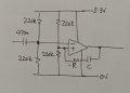
Here's a circuit that might be worth experimenting with. I was working on a mains zero-crossing detector which has to be phase-correct and amplitude-independent, and I think it might work for you.
The IC is a comparator with push-pull output. You'll have to experiment with R and C values, I only need it to work at 50Hz, but you need a wider frequency range. As a starting point try RC time constant = quarter of a period at the highest frequency you want to measure.
You might need amplification on the input, but try it without. Also try with and without filtering,
Ah, this combo seems to work pretty well. I've tried all sorts of combos for how much gain to add in the 2nd stage. This seems to be the sweet spot. 34x gain in the 1st stage and 5.7x gain in the 2nd. That makes it so tuning the low E string is fairly stable and also keeps the trail of the high E string a little longer than what I had before in our PCB.
I'm seeing something strange and not sure exactly why. Yesterday I tried a number of different gain multipliers at the different sides of the LM358 and finally settled on this one as performing "best" in terms of the ESP32 being able to recognize the frequencies via the ADC. I was considering how jittery it was and also how long the highest string on a guitar would last longer (tail off the longest). I think the trick is being able to amplify the "quietest" string (high strings have less energy) so that they can be measured for a longer amount of time. I tried doing all the gain in just one stage but it seems to perform better split into two.
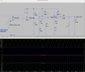
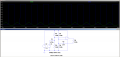
Here's my latest circuit that I've settled on but one thing that's confusing to me is that with a 3.3V Zener, the output voltage gets clamped at 2.5V. When I move up to a 3.9V Zener, the voltage is clamped at 3V. I'm measuring with DC coupling on my oscilloscope both the 1st stage (top plot) and 2nd stage (bottom plot). The incoming signal in this case is me just strumming my telecaster across all strings and it's, say, around 250mV AC input.
This is a bit different that what LTspice is showing and I'm just wondering why this might be happening? I've just double-checked all of the resistors on my breadboard with my DMM to confirm they are the right values.
I switched my DMM into ammeter mode and put the probes between R8 and the cathode of the 3.9V Zener and am only measuring a max of about 275uA. Maybe, this is why? It doesn't even come close to the normal operating range of the Zener?
Interestingly, if I put a 4.3V Zener, the output voltage to the ADC pin gets clamped to 3.3V. But my measurements in ADC get slammed to the max. So I think maybe a 3.9V Zener is the sweet spot for this particular use?
Interestingly, if I put a 4.3V Zener, the output voltage to the ADC pin gets clamped to 3.3V. But my measurements in ADC get slammed to the max. So I think maybe a 3.9V Zener is the sweet spot for this particular use?
As I mentioned before with a 5 volt supply the max output of the 358 is appx 3.5 volts.
Would need to lower the value of R8 significantly for a 3.3 volt zener.
At 9 volts R8 is probably OK.
I'm seeing something strange and not sure exactly why. Yesterday I tried a number of different gain multipliers at the different sides of the LM358 and finally settled on this one as performing "best" in terms of the ESP32 being able to recognize the frequencies via the ADC. I was considering how jittery it was and also how long the highest string on a guitar would last longer (tail off the longest). I think the trick is being able to amplify the "quietest" string (high strings have less energy) so that they can be measured for a longer amount of time. I tried doing all the gain in just one stage but it seems to perform better split into two.
Here's my latest circuit that I've settled on but one thing that's confusing to me is that with a 3.3V Zener, the output voltage gets clamped at 2.5V. When I move up to a 3.9V Zener, the voltage is clamped at 3V. I'm measuring with DC coupling on my oscilloscope both the 1st stage (top plot) and 2nd stage (bottom plot). The incoming signal in this case is me just strumming my telecaster across all strings and it's, say, around 250mV AC input.
This is a bit different that what LTspice is showing and I'm just wondering why this might be happening? I've just double-checked all of the resistors on my breadboard with my DMM to confirm they are the right values.
@sghioto Ok, that makes more sense. If I switch to a 330R and 470n cap, that keeps the value of my LPF the same and it also increases the current that the Zener sees. A 3.3V Zener in this case is clamping at 3.0V which is great.
@eetech00 Ah, that makes more sense. Thanks for the clarification. 250 pp is fine in this case just for getting a general idea. That's what I'm seeing on my scope too when I strum hard on my tele.
@sghioto Ok, that makes more sense. If I switch to a 330R and 470n cap, that keeps the value of my LPF the same and it also increases the current that the Zener sees. A 3.3V Zener in this case is clamping at 3.0V which is great. View attachment 344970
@eetech00 Ah, that makes more sense. Thanks for the clarification. 250 pp is fine in this case just for getting a general idea. That's what I'm seeing on my scope too when I strum hard on my tele.
Oh right, this is in comparator mode. I tried something similar a few days ago and the biggest problem was that when the guitar signal tapered off, the comparators went away and so tuning only worked for a very short time.
Oh right, this is in comparator mode. I tried something similar a few days ago and the biggest problem was that when the guitar signal tapered off, the comparators went away and so tuning only worked for a very short time.

 Facebook
 Google
 GitHub
 Linkedin