Facebook
 Google
 GitHub
 Linkedin
Thanks! I got it to work just fine. Now I would like to turn a LED on when light is present. Basically a reverse of the above project.
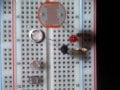
Here you go..... this works opposite of my first circuit....
My .02
Attachments
-
 3.2 KB Views: 117
 , The circuit WILL WORK if you have a specific photocell to use, I tried the circuit with 4 photocells and it will only work with one out of four, my circuit works with all 4.....