Simple noninverting Op Amp circuit with arduino input signal

Thread Starter

BullfroG21

Joined Nov 22, 2016
4
Hi everyone,
I am currently trying to start working on some project with circuits, but unfortunately i am already failing in building a basic non inverting op amp circuit...


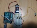
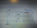
If i am "rebuilding" this circuit the 9V power source is an single supply battery, and the 3.5V input Signal as an Arduino Signal Output ( - is Ground or Input pin). The Op amp is actually an LM358.

Unfortunately my circuit is putting an max output, without any input signal at all.
Any ideas?

kind regards
 

Attachments

Last edited:

#12

Joined Nov 30, 2010
18,224
You have built a circuit with a gain of 2.
Unfortunately my circuit is putting an max output, without any input signal at all.
Odd, the drawing shows an input of 3.5 volts, a gain of 2, and an output of almost exactly 7 volts.
What's wrong with that?
 

shteii01

Joined Feb 19, 2010
4,644
If you don't have an input to op amp, then the input pin is "floating". This is not desirable, particularly in your case because you are new, inexperienced and don't really know what you are doing.

The other possibility is that the chip is broken. Fried by your or static electricity.

In everything I wrote so far I assumed that you actually connected things correctly.

You can connect op amp input to ground. That would be feeding it 0 volts. You should observe 0 volts or near that at the op amp output. If you see more than 10 mV at the output, I bet the op amp is fried.
 

shteii01

Joined Feb 19, 2010
4,644
You have built a circuit with a gain of 2.

Odd, the drawing shows an input of 3.5 volts, a gain of 2, and an output of almost exactly 7 volts.
What's wrong with that?
What Hashtag One Two said.
You have 3.5 volt input. Your op amp is configured for the gain of 2. 3.5*2=7 volt. You are showing 6.99 volts. Close enough.
 

Thread Starter

BullfroG21

Joined Nov 22, 2016
4
Hi,
Thank you for your very quick respond.

Yes, the simulations results are correctly, attached some photos from my real circuit.

The second Resistor is not on the V+ input, it just looks like it :)

Thank you for your effort
with kind regards
 

Attachments

Thread Starter

BullfroG21

Joined Nov 22, 2016
4
Hi,
Thank you for your very quick respond.

Yes, the simulations results are correctly, attached some photos from my real circuit.

The second Resistor is not on the V+ input, it just looks like it :)

Thank you for your effort
with kind regards

In this circuit i got a maximum voltage with or without an input signal at all, is my wiring correct?
I checked the op amp and it seems to be fine.
 

Thread Starter

BullfroG21

Joined Nov 22, 2016
4
Sorry for my imprecise description:

I put one time an input signal into the non-inverting input (Arduino input ca. 5V) and an another time I didn't put any input signal on it, in both cases the result on the output was the same (7-8V). I measured the output signal with an potentiometer (connected to the loose yellow cable).

I checked the op amp's like shteii0 described it and they seemed to be fine.http://forum.allaboutcircuits.com/members/shteii01.75980/

kind regards
 

#12

Joined Nov 30, 2010
18,224
I put one time an input signal into the non-inverting input (Arduino input ca. 5V) and an another time I didn't put any input signal on it,
You did not answer the question. There is no such thing as, "no signal at all". The input is either connected to a voltage or it is producing its own input by having no path for the input bias current to flow. Which is it?
 
Top