Facebook
 Google
 GitHub
 Linkedin
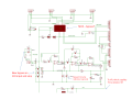
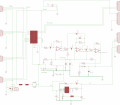
I've built a neat little ultrasonic sensing circuit (reference link below for previous post, and amplifier diagram attached, for those who are curious), and in *most* applications, it works fine. I've deployed a couple of these in some friends' garages, and so far, everything worked fine for everyone.
Then I shipped one to a friend in Maryland, 3000 miles away, and it doesn't work. I can't plug in an oscilloscope at that distance, but my instinct is that he's got a power input dirty enough that my 120VAC to 24VDC power supply isn't smoothing it well enough. From what I can see from what the machine is doing, it looks like I'm getting an 8khz signal overlaid on the wave. (I recognize the signs from early in development, when I was using low-cost power supplies that didn't produce a clean output.)
So I'm trying to figure out how to economically solve this problem. Some challenges:
- I can't duplicate my friend's problem locally. I could, theoretically, ship him my oscilloscope and get readings for what his wall power looks like, and what the 24V output looks like. But I'd rather ship him something to fix the problem, if possible.
- I don't have unlimited money for this. I could add a 24VDC switching voltage regulator with all of the requisite parts, and go from using a 24V power supply to using a 36V power supply. That would probably fix it, but the cost would be significant. Similarly, if I have to start adding in $20 inductors and $43 capacitors, it's not going to work.
I guess the optimal solution would be to use what's already on the board, just try to figure out where to insert some capacitors to smooth things out enough to make this work. I've attempted a couple of variations on the theme of "low pass filter" to try to make it work, but I'm not getting usable results from those.
Thoughts? I'm at a loss here. Thanks.
Dan
https://forum.allaboutcircuits.com/...output-for-a-d-conversion.122866/#post-987433
Attachments
-
 339 KB Views: 32


")