

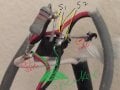
This alarm system however, activated by itself all the time. I believed the battery continually charged and the power surged that make this interruptedly alarm on and off uncontrollably.
Attachments
-
 114.2 KB Views: 25
Thank you Alec_t,Welcome to AAC!
That circuit won't work as you want it to. I suggest you read up about how SCRs are triggered and switched off.
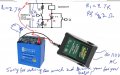
That doesn't make sense. S1 is in the wrong place. When you apply power, the gate is pulled up to the supply which will turn the SCR on; regardless of whether you have the charger connected or not.It does work very well without the "Battery Tender" charger. I can turn on the S1 to activate the alarm.

How is an alarm supposed to protect two children who should never be left home alone to begin with?to protect my two little boys when they are at home alone
 src. http://tinyurl.com/y59wdm8c
You must have the gate floating when S1 is opened. Put a resistor from gate to ground to prevent the gate from picking up spurious signals.Do you or anyone can help me with a simple device to connect from the charging battery to the unit?


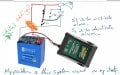
The specs say it switches to float charging after the battery is charged.My main concern at this moment is that will this Battery Tender constantly charge my gel battery "Mighty Max 6A 12volt) in the attic with constantly charging and would not destroy my battery? (Junior?) 12v and 750mA.


by Jake Hertz

by Jake Hertz

by Duane Benson