 Facebook
 Google
 GitHub
 Linkedin
Hello,
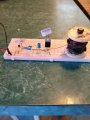
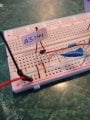
Can someone possibly help me to see if I have this simple circuit correct?
This is not about if any units work or not. It is only about the circuit and circuit only and nothing else.
Any person who actually knows this simple rudimentary trivial circuit will answer it instantly even with their eyes closed without all of my yap yap yap below and the rest... oh my. Lets find out, shall we?
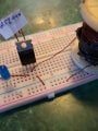
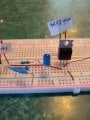
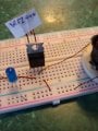
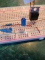
The Hall sensor is A3144. In the picture I consider its left pin as supply, the middle as the ground and the right as output.
The transistor is Mosfet IRFZ44N (npn type). I consider the left pin as the base, the middle as the drain and the right pin as the source.
The resistor with the blue tape is 1K ohm and the other one to the LED is 230 ohm.
The coil in the picture is the load I want to feed off and on by passing a magnet in front of the Hall sensor. The power will be hooked up the two wires red to positive and black to negative of a battery DC terminals.
I have considered that the Front of the Hall sensor is facing the camera (facing you) in the picture. I consider the face as the part that is tapered, not as wide as the back of it. The back which you can't see is the wider larger square part not visible to the camera.
The Mosfet's flat side is hiding behind I you can't see. I have taken enough picture so to avoid any back and forth which I will guarantee I will fail. I will get everything but an answer and that is where most people go. Finding holes is in the nature of language and the clever safely puts it to use... you know what about this and that and what about the other and on and on. Everlasting holes.
Furthermore, my question is about the circuit itself, not about if the coil is right coil or if the sensors actually work or if the LED is burnt or if the resistors really are still good or if the wires are too old or the bread board is too used up loose or what type of power I am using or god knows what will come my way.
Thank you in advance for you help.
Can someone possibly help me to see if I have this simple circuit correct?
This is not about if any units work or not. It is only about the circuit and circuit only and nothing else.
Any person who actually knows this simple rudimentary trivial circuit will answer it instantly even with their eyes closed without all of my yap yap yap below and the rest... oh my. Lets find out, shall we?
The Hall sensor is A3144. In the picture I consider its left pin as supply, the middle as the ground and the right as output.
The transistor is Mosfet IRFZ44N (npn type). I consider the left pin as the base, the middle as the drain and the right pin as the source.
The resistor with the blue tape is 1K ohm and the other one to the LED is 230 ohm.
The coil in the picture is the load I want to feed off and on by passing a magnet in front of the Hall sensor. The power will be hooked up the two wires red to positive and black to negative of a battery DC terminals.
I have considered that the Front of the Hall sensor is facing the camera (facing you) in the picture. I consider the face as the part that is tapered, not as wide as the back of it. The back which you can't see is the wider larger square part not visible to the camera.
The Mosfet's flat side is hiding behind I you can't see. I have taken enough picture so to avoid any back and forth which I will guarantee I will fail. I will get everything but an answer and that is where most people go. Finding holes is in the nature of language and the clever safely puts it to use... you know what about this and that and what about the other and on and on. Everlasting holes.
Furthermore, my question is about the circuit itself, not about if the coil is right coil or if the sensors actually work or if the LED is burnt or if the resistors really are still good or if the wires are too old or the bread board is too used up loose or what type of power I am using or god knows what will come my way.
Thank you in advance for you help.
Attachments
-
 3.2 MB Views: 31
 -
 2.9 MB Views: 29
 -
 2.8 MB Views: 30
 -
 2.9 MB Views: 25
 -
 2.7 MB Views: 24
 -
 2.9 MB Views: 23
 -
 2.7 MB Views: 23
Last edited:


