When no pedals are pushed, the output should be 2.5V; this represents coasting. What the problem is, there is too much amplification of the input. Change the gain to half its value by decreasing the gain resistor to half its value (10k) or put in a voltage divider.
I need to go now, I'll be back in a few hours.
Changed the resistor value and found out that the lower the closest I was getting to the voltage I needed (2.5v), but the only way to reach the 2.5v, and therefore keep the range between 0v and 5v was to remove the feedback resistor. Not sure if this is a good idea, but it works in the simulation, even with the 5-terminal virtual opamp.
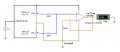
This is the final working circuit:
It's working well in this configuration. At the beginning LCD3 proposed the pots in the direction you mention, but then both pots where doing the exact same function (adding the output basically). I turned one around, because I knew by testing these past weeks that you needed to do it this way, and now one pedal adds to the output while the other subtracts; that's how it should work. When you press both, or leave both intact, the change that one produces in one direction (e.g. adding voltage/resistance) is perfectly balanced by the other subtracting the same amount; leaving the device virtually without change.
I don't think it needs more adjustments; just worried about taking out the feedback resistor, and if the device will be able to provide the extra 5v for the opamp.
No, a comparator will not work. A comparator has 2 defined outputs (high and low); + being a higher voltage potential than the -, and the other way around. It will not give you a range of voltages.
It's working well in this configuration. At the beginning LCD3 proposed the pots in the direction you mention, but then both pots where doing the exact same function (adding the output basically). I turned one around, because I knew by testing these past weeks that you needed to do it this way, and now one pedal adds to the output while the other subtracts;
Then WHY did you tell me, when I asked abouit what you meant by "balanced", that, "Each pot on each pedal is at 25% when it's not pressed (I guess that's 5Kohms), and at 75% when it's fully pressed (around 15Kohms). "?
This is NOT how you have them hooked up because you have modified the pedals. Now one pot is at 25% when not pushed and the other is at 75% when not pushed. One increases as it's pushed and the other decreases as it's pushed.
So what are you going to do when you switch back to a car configuration? Remodify your pedals?
I don't think it needs more adjustments; just worried about taking out the feedback resistor, and if the device will be able to provide the extra 5v for the opamp.
Taking out the feedback resistor makes the opamp a voltage follower which, in this case, means that it will output the average of the two pedal positions, which is what you want. With the mod you have made to the pedal, when one is pressed you are averaging 25% and 25% and when the other is pressed you are averaging 75% and 75%. When neither is pressed you are averaging 25% and 75%.
Without the feedback resistor, you could remove (remove, not replace it with a shortcircuit like you did the feedback resistor) the other resistor tied to the inverting input as it is having little effect.
No, a comparator will not work. A comparator has 2 defined outputs (high and low); + being a higher voltage potential than the -, and the other way around. It will not give you a range of voltages.
Then WHY did you tell me, when I asked abouit what you meant by "balanced", that, "Each pot on each pedal is at 25% when it's not pressed (I guess that's 5Kohms), and at 75% when it's fully pressed (around 15Kohms). "?
This is NOT how you have them hooked up because you have modified the pedals. Now one pot is at 25% when not pushed and the other is at 75% when not pushed. One increases as it's pushed and the other decreases as it's pushed.
So what are you going to do when you switch back to a car configuration? Remodify your pedals?
Both are at 25% when released; but if you think about it's just relative, because 25% towards the top pin is 75% towards the bottom pin. So when I say they are at 25% I mean towards the same direction.
But basically you are right, when the pedals act as normal racing pedals one of them needs to be turned around; in the position you proposed. That's how they were originally wired.
I'm planing on building a circuit with the original wiring and the new added circuit, and add a switch to choose between both modes. So, when the switch is in racing mode, the potentiometers are crossed (in the position you said) and will avoid the new circuit going directly to the device; and when the switch is in rudder mode then the pots will be in the diagram's position and will pass through the new circuit before reaching the device.
Taking out the feedback resistor makes the opamp a voltage follower which, in this case, means that it will output the average of the two pedal positions, which is what you want. With the mod you have made to the pedal, when one is pressed you are averaging 25% and 25% and when the other is pressed you are averaging 75% and 75%. When neither is pressed you are averaging 25% and 75%.
At the moment, with the last modification, I'm getting 2.5v when both pots are at 25% (the minimum they allow) and the same voltage if they are pressed at the same rate; I get 1.250v when the top pot is moved to 75% (which is the max allowed); and I get 3.750v when the bottom pot is moved to 75%. If both pedals are moved, then I get the difference (above 2.5v if the top is moved more, and below 2.5v if the bottom is moved more). It seems to be perfect this way.
Without the feedback resistor, you could remove (remove, not replace it with a shortcircuit like you did the feedback resistor) the other resistor tied to the inverting input as it is having little effect.
Finally got the opamp -I couldn't find the MC33201 so got another one (an UA741CN). I tested it first on a breadboard and it's not working.
I set the positive to 5v with a DC power supply and the output is stuck 2v; except when I move the 2nd pot, which changes the voltage to 3.5v when I move it towards the center. The other pot does absolutely nothing.
Not sure if I got the proper opamp. Maybe this one needs more than 5v Vcc.
A 741 op-amp requires a dual voltage supply (usually +15 V and -15 V). If you don't have a dual supply, it won't work the way you want it to. The offset pins are to allow an adjustment so the when both inputs are equal, the output is 0 V. See the datasheet for the proper component connection.
A 741 op-amp requires a dual voltage supply (usually +15 V and -15 V). If you don't have a dual supply, it won't work the way you want it to. The offset pins are to allow an adjustment so the when both inputs are equal, the output is 0 V. See the datasheet for the proper component connection.
Thanks, since they didn't have the one you recommended I just asked for any opamp. I asked him for one with a low Vcc voltage, but the guy was a bit pissed off for not giving him the exact reference of what I wanted.
I've been looking through this list of OP-AMPS searching if any of the single ones were available in my local shop. The only ones seem to be the 15v ones, I can't find any that would work at 5v except this one LM748.
I've been looking through this list of OP-AMPS searching if any of the single ones were available in my local shop. The only ones seem to be the 15v ones, I can't find any that would work at 5v except this one LM748.
The LM748 also operates with a dual power supply, from +5 V and -5 V to +15 V and -15 V. It is best to have equal voltages away from ground.
About all the list does is tell you how many op-amps are in each IC. It doesn't have a lot of the important information, such as single supply, rail-to-rail output. I need to look at each item in the list, so I'll get back to you on which ones you could use (from the list).
Finally got the opamp -I couldn't find the MC33201 so got another one (an UA741CN). I tested it first on a breadboard and it's not working.
I set the positive to 5v with a DC power supply and the output is stuck 2v; except when I move the 2nd pot, which changes the voltage to 3.5v when I move it towards the center. The other pot does absolutely nothing.
Not sure if I got the proper opamp. Maybe this one needs more than 5v Vcc.
This is actually about the performance you would expect. The 741 can typically produce output voltages that are within roughly 1V to 3V of the supply rails. Thus, if powered between 0V and 5V, the highest voltage you can get out of it is going to be somewhere between 2V and 4V and the lowest voltage you can get out of it is going to be somewhere between 1V and 3V. Notice the overlap in those ranges -- this means that you could get a part that does nothing but puts out a fixed 2.14V that is insensitive to your inputs altogether and it would still be operating within spec!
For what you are doing, you would also like it to be low power. Most of the other performance specs are not very important to you.
Put this into Google and you'll get quite a few hits:
low power single-supply rail-to-rail opamps
A couple that pop out right away are the Microchip MCP6241 and the TI OPA344. Looking at Digi-Key's product selector, you have literally tens of thousands to choose from. You can get them from under a quarter to about three dollars. You can get supply currents that are down under a microamp. So lots to choose from.
You don't need to identify every opamp that would work. Remember, you only need to get your hands on ONE that works!
The LM324 is a pretty ubiquitious opamp -- that won't work very well for you. The output only gets to within about 1.5V of the upper rail.
Does the store where you are buying your opamp from have any kind of online listing of what they stock?
EDIT: I didn't realize when I wrote this that it wasn't the OP I was responding to. It makes perfect sense for LDC3 to spend some time putting together a partial list since he doesn't know which opamps might be available to the OP.
Also found yesterday night a website that allows me to choose the characteristics of the opamps and then gives me a list. I basically looked for a 5v one and there were only 2 available at my local shop: the TL071 and the TL081
I used the TL074 and TL084 (the quad versions of the TL071 and TL081) in the first product I designed and was quite satisfied. That entire product consumed under 1mA of current, so you've got a chance at powering your circuit without having to bring in external power.
Went through your list and they only have 1 in my local shop, the LM324N. I don't like it for this project because I prefer a DIP8 single opamp, but I'll get it anyway to keep at home for other tests and experiments.
I used the TL074 and TL084 (the quad versions of the TL071 and TL081) in the first product I designed and was quite satisfied. That entire product consumed under 1mA of current, so you've got a chance at powering your circuit without having to bring in external power.
So far I think the TL081 is my best option, along with the TL071 (though it's more expensive); can't find anything else that would meet the specifications and is available at the shop.
The only problem is that I'm unable to see in this datasheet if the TL081 meets the 3 conditions you posted above:
The TL081 is not rail-to-rail and may only get you to within a volt or so of the supply rails. But that may be workable since you seem to be interested primarily in output voltages that are between 25% and 75%, or a range of about 2.5V. If you can get to within 1.25V of each rail, then you have a workable signal. Since you already need to use a light loading, you may well get that. Not something I would recommend in a production design, but for a one-off design it's an option.
Where is it that you are located? Do you have any mail-order options for getting components?
If you look at the spec for Output Voltage Swing, you will see that it says that the minimum is ±12V but the typical is ±13.5V. Looking at the conditions for which that spec was written for, you see that the supply rails are ±15V. That means that the amplifier output can typically get to within 1.5V of each rail, but they only guarantee that it can get within 3V. Hence it can't get very close to the rails and, therefore, is not a rail-to-rail opamp. Note that rail-to-rail opamps are pretty proud of the fact and so you will see it prominantly stated that they are rail-to-rail. Conversely, if they don't state it clearly, it almost certainly isn't rail-to-rail.
No, if the latter applies and the one you get can only get within 3V of the rail, that makes it worthless for you. For that reason alone you really should use a different amp. But if it's the only one you can get, the you have to rely on two things: (1) most amps will be closer to the typical value, which still might not be good enough for you but is getting close, and (2) you are only loading the output very lightly and the specs assume a loading of 10kΩ (you probably have at least 10x that since the system is intended to read from 20kΩ pots). So you should get at least a bit closer to the rails than normal. But it will be marginal and you really should use a different part if you can get your hands on one.
 Facebook
 Google
 GitHub
 Linkedin
")