Simple design puzzle

Thread Starter

adam555

Joined Aug 17, 2013
858
Since I put 5 V across the pots, the pots act as a voltage divider. I could refer to having 0 Ω or 5 V when the pot is at the top end, and the resistance of the pot or 0 V when at the other end.
Circuits don't see resistance, they see voltage or current, so it is better to express the items as either a voltage output or a current output.
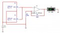
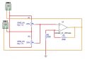
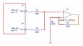
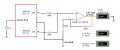
Another question more... which would be the 3 connectors?
 

LDC3

Joined Apr 27, 2013
924
Where I have the 5 V, where I have the ground, and the output of the op-amp. If you want a voltage other than 0 V for ground, you will need to remove the wire from the pots to the resistor connected to the op-amp. The connections are represented by arrows.
 

Attachments

Thread Starter

adam555

Joined Aug 17, 2013
858
Just tried your first circuit, and it seems to work pretty well.

I did this, which is basically what you posted, but changing the resistors to 20K, turning one potentiometer around, and removing the 2 resistors at the right side of the potentiometers.


It does exactly what it should. The potentiometers on the pedals go from 25% to 75%, and both are at 25% in the initial position. So, when no pedal is pushed I get 5V, when the left pedal is pushed I get 7.5V, and when the right pedal is pushed I get 2.5V... Ideal!!!

Now I'm going to try your second circuit to test the balanced outputs. But my main worry now is how to implement all this into the pedals. :(
 

Attachments

bertus

Joined Apr 5, 2008
22,277
Hello,

I see you have forgotten R3 and R4 in the schematic, made by LCD3.
Without them the potmeters might burn, when one is very close to the +5 and the other very close to the GND.

Bertus
 

Thread Starter

adam555

Joined Aug 17, 2013
858
Where I have the 5 V, where I have the ground, and the output of the op-amp. If you want a voltage other than 0 V for ground, you will need to remove the wire from the pots to the resistor connected to the op-amp. The connections are represented by arrows.


I tried this, but it's not working; both ohmeters are static at a few gigaohms nomatter where you set the pots.

I'm pretty sure it's because the opamp is not getting any current, and that's something that has been worrying me from the beginning; because I assume it will need some voltage to operate, apart from the one that measures the resistance. Where am I going to get it from?
 

Attachments

Thread Starter

adam555

Joined Aug 17, 2013
858
Hello,

I see you have forgotten R3 and R4 in the schematic, made by LCD3.
Without them the potmeters might burn, when one is very close to the +5 and the other very close to the GND.

Bertus
Thanks Bertus,

Didn't know the reason why they were there, so I took them off. I'll put them back
 

LDC3

Joined Apr 27, 2013
924


I tried this, but it's not working; both ohmeters are static at a few gigaohms nomatter where you set the pots.

I'm pretty sure it's because the opamp is not getting any current, and that's something that has been worrying me from the beginning; because I assume it will need some voltage to operate, apart from the one that measures the resistance. Where am I going to get it from?
You are trying to measure the resistance through the op-amp, which has high impedance inputs, which means that the resistance will always be very high. Move the leads to the input side of the op-amp to measure the resistances of the pots.

If you look at the connection from the console to the controls, you will notice that there is a line for ground, a line for a positive voltage and a line for each signal on the control. You should have enough power for the op-amp.
 

Thread Starter

adam555

Joined Aug 17, 2013
858
You are trying to measure the resistance through the op-amp, which has high impedance inputs, which means that the resistance will always be very high. Move the leads to the input side of the op-amp to measure the resistances of the pots.

If you look at the connection from the console to the controls, you will notice that there is a line for ground, a line for a positive voltage and a line for each signal on the control. You should have enough power for the op-amp.
Yes, it has 4 wires (black, red, green and yellow): green and yellow are for each signal, and I suppose black and red are ground and positive respectively. So, where do I connect those 4 wires in this circuit (I guess it won't matter if yellow and green go together, since we're only using 1 axis)?


I don't think I have any opamp at home but I suppose the one I'll buy will have 5 pins, and not 3 like the virtual one I'm using in my examples; is this correct?

By the way, any particular opamp you would recommend for this project?
 

Attachments

Last edited:

LDC3

Joined Apr 27, 2013
924
Yes, it has 4 wires (black, red, green and yellow): green and yellow are for each signal, and I suppose black and red are ground and positive respectively. So, where do I connect those 4 wires in this circuit (I guess it won't matter if yellow and green go together, since we're only using 1 axis)?

I don't think I have any opamp at home but I suppose the one I'll buy will have 5 pins, and not 3 like the virtual one I'm using in my examples; is this correct?

By the way, any particular opamp you would recommend for this project?
I had a feeling you were going to ask that. Since I am not certain of the power supply, I found this one that can operate up to 12 V and provide rail to rail output. It can provide up to 80 mA of current (depends on the load) and uses about 1 mA (for each amplifier in the IC). You would connect the input pins of any unused amplifier to ground and the output to a 10 kΩ (or higher) resistor to ground.

Connect the positive power to Vcc on the IC (pin 7, 8 or 4, depends on which on you get) and the ground to Vee (pin 4 or 11). You would also connect the power and ground to the pots. The output of the op-amp would be the voltage signal for your speed.
 

Thread Starter

adam555

Joined Aug 17, 2013
858
I had a feeling you were going to ask that. Since I am not certain of the power supply, I found this one that can operate up to 12 V and provide rail to rail output. It can provide up to 80 mA of current (depends on the load) and uses about 1 mA (for each amplifier in the IC). You would connect the input pins of any unused amplifier to ground and the output to a 10 kΩ (or higher) resistor to ground.

Connect the positive power to Vcc on the IC (pin 7, 8 or 4, depends on which on you get) and the ground to Vee (pin 4 or 11). You would also connect the power and ground to the pots. The output of the op-amp would be the voltage signal for your speed.
Would the connections go like this then? (please note that it mixes things a lot)


Or like this; substituting the representation of the opamp with the actual IC:


Haven't tested any of this. I don't have time to do it today, but I'll give it a try tomorrow.

Thanks a lot for all your help; I've been trying to combine those 2 damn potentiometers for 2 weeks. :p
 

Attachments

LDC3

Joined Apr 27, 2013
924
Would the connections go like this then? (please note that it mixes things a lot)

Or like this; substituting the representation of the opamp with the actual IC:

Haven't tested any of this. I don't have time to do it today, but I'll give it a try tomorrow.

Thanks a lot for all your help; I've been trying to combine those 2 damn potentiometers for 2 weeks. :p
The first image is a schematic and shows you where the wires are connected.
The second image didn't show, but I'm guessing that it looks like a layout since you are using the location of the actual connections to place the wire. Very similar to a breadboard.
 

Thread Starter

adam555

Joined Aug 17, 2013
858
The last configuration didn't work; so I went a step back and tried again.

This one works with the 3 terminals virtual opamp (2 imputs and output only), but it doesn't work with the 5 terminals virtual opamp in the schematic below; the voltage starts at 4.34V when both pedals are at 25% (the initial position), and it goes down as it should to 2.5V when the top pedal is pushed to 75%, but stays still at 4.34V when the bottom pedal is pushed instead of going up to 7.5V; which is what it does with the 3 pin virtual opamp. Is this something I did wrong, or just a problem with the simulator?


Oh, I also measured the voltage coming through the cables, and found out that the colors don't match the typical usage: Black is positive 5V, Red is ground, and Green and Yellow are the axis (with 2.5V between each and ground).
 

Attachments

WBahn

Joined Mar 31, 2012
30,062
It sounds like what you are really wanting is a differential amplifier.

If both pedals are pressed the same amount, then you want the output to be the same as if they weren't pressed at all, right? If not, then pressing them equally will be interpreted as being either left or right rudder, and why would you want that.

So get a 5V rail-to-rail single-supply opamp so that you can power it off the 5V that is supplied by the cable. Another option is to make a box that the two pedal units plug into and that then plugs into your game unit. This would allow you to bring in auxiliary power and make it so that you wouldn't have to make any modifications to your pedals at all.

Try something like this in your simulation:


The opamps you can get in quad packages (four amps in one IC package) and the resistors you can get in arrays with four identical resistors in a package (which is why I chose to put the two resistors in parallel). The purpose of the third pot is to provide a trim capability so that you can adjust the output when the pedals are in the "neutral" position (probably when neither is being depressed at all) that you get 2.5V out. It should be adjusted to the center of it's range, giving you an effective resistance of 10kΩ to a 2.5V reference. With the feedback resistor also being 10kΩ, you will have a gain of 0.5 about the reference voltage.

The first two opamps are there to buffer the stock pots so that you don't have to deal with loading effects.

One concern that I have is that your game console may not be able to provide much current beyond what is needed for the pots that it is expecting to have connected to it.
 

Attachments

Thread Starter

adam555

Joined Aug 17, 2013
858
It sounds like what you are really wanting is a differential amplifier.

If both pedals are pressed the same amount, then you want the output to be the same as if they weren't pressed at all, right? If not, then pressing them equally will be interpreted as being either left or right rudder, and why would you want that.

So get a 5V rail-to-rail single-supply opamp so that you can power it off the 5V that is supplied by the cable. Another option is to make a box that the two pedal units plug into and that then plugs into your game unit. This would allow you to bring in auxiliary power and make it so that you wouldn't have to make any modifications to your pedals at all.

Try something like this in your simulation:


The opamps you can get in quad packages (four amps in one IC package) and the resistors you can get in arrays with four identical resistors in a package (which is why I chose to put the two resistors in parallel). The purpose of the third pot is to provide a trim capability so that you can adjust the output when the pedals are in the "neutral" position (probably when neither is being depressed at all) that you get 2.5V out. It should be adjusted to the center of it's range, giving you an effective resistance of 10kΩ to a 2.5V reference. With the feedback resistor also being 10kΩ, you will have a gain of 0.5 about the reference voltage.

The first two opamps are there to buffer the stock pots so that you don't have to deal with loading effects.
This one seems to work pretty well, but with the 3 terminals opamp. If I change the 3 terminals virtual opamp for the 5 terminals one (as in my previous post) it stops working.


I'm also wondering about those 7.5V output; since the positive is just 5V.

One concern that I have is that your game console may not be able to provide much current beyond what is needed for the pots that it is expecting to have connected to it.
Yes, I was also concern about that. That's the main reason why I was trying to do it without any components that needs extra power supply.
 

Attachments

Last edited:

WBahn

Joined Mar 31, 2012
30,062
Your 3-terminal opamp doesn't have a power supply and so it assumes it is an ideal opamp and can generate whatever voltage is needed.

Your 5-terminal opamp does have a power supply, so the model for it knows about the power rails. The model appears to have some knowledge of how close the output can get to the rail, as well, which you may be able to change since different opamps are different in this regard.

I don't know what you mean by "balanced" when you are talking about the pot settings. I'm assuming that the pedals are electrically identical so that if both are pressed the same amount you get the same output at their respective wiper terminals. Or, for that matter, I'm not sure how you are planning to use the two pedals as rudder pedals. By that, I mean what the pilot is going to do -- do they only press one pedal at a time? Does that mean that you don't care what happens if they have both pedals pressed at the same time, say the left one one-third of the way and the right one two-thirds of the way? What if they have both pressed half way? Could you describe that more precisely, please?
 
I need 2 potentiometers to act as one.

You are trying to fly a boat.

You have not properly defined the problem.
That is the universal amateur design flaw.

This has been solved many times, many ways.

You said yourself, you are trying to replicate an existing solution.

Define your unique situation.
Discover how it has not been addressed correctly in the art.

If it has been done before...do something else.
 

Thread Starter

adam555

Joined Aug 17, 2013
858
Your 3-terminal opamp doesn't have a power supply and so it assumes it is an ideal opamp and can generate whatever voltage is needed.

Your 5-terminal opamp does have a power supply, so the model for it knows about the power rails. The model appears to have some knowledge of how close the output can get to the rail, as well, which you may be able to change since different opamps are different in this regard.
So, how do I get the 5-terminal circuit to work; changing the resistors?

I don't know what you mean by "balanced" when you are talking about the pot settings. I'm assuming that the pedals are electrically identical so that if both are pressed the same amount you get the same output at their respective wiper terminals. Or, for that matter, I'm not sure how you are planning to use the two pedals as rudder pedals. By that, I mean what the pilot is going to do -- do they only press one pedal at a time? Does that mean that you don't care what happens if they have both pedals pressed at the same time, say the left one one-third of the way and the right one two-thirds of the way? What if they have both pressed half way? Could you describe that more precisely, please?
By "balanced" I meant that both pots are in the same position. Each pot on each pedal is at 25% when it's not pressed (I guess that's 5Kohms), and at 75% when it's fully pressed (around 15Kohms). You're not meant to push both at the same time, but in the last working circuit it won't matter if you do -which is exactly how it's meant to behave-, since if you press both the same amount (you balance them) the output from the opamp is the same as if none was pressed. And, if one is pressed to 50% and the other to 40%, the result would be as if only the first is pressed to 35% (the initial 25% + the 10% difference).
 

WBahn

Joined Mar 31, 2012
30,062
So, how do I get the 5-terminal circuit to work; changing the resistors?
How should I know? I don't even know what simulator you are using.

By "balanced" I meant that both pots are in the same position. Each pot on each pedal is at 25% when it's not pressed (I guess that's 5Kohms), and at 75% when it's fully pressed (around 15Kohms). You're not meant to push both at the same time, but in the last working circuit it won't matter if you do -which is exactly how it's meant to behave-, since if you press both the same amount (you balance them) the output from the opamp is the same as if none was pressed. And, if one is pressed to 50% and the other to 40%, the result would be as if only the first is pressed to 35% (25% + the 10% difference).
This is not consistent with the circuit you are presently using. If both pots start out at the same amount and then change in the same way as you press the pedals, then you will find that one of your pots is inserted into your schematic backwards. Look at the wiper arrows -- see how one points toward the ground connection and the other points toward the 5V supply connection. Flip them around and you will see that as when they are unpressed you have either a min/max at the amplifier output (depending on which way you connect them) and that the output moves in the same direction regardless which pedal is pushed.
 

LDC3

Joined Apr 27, 2013
924
The last configuration didn't work; so I went a step back and tried again.

This one works with the 3 terminals virtual opamp (2 imputs and output only), but it doesn't work with the 5 terminals virtual opamp in the schematic below; the voltage starts at 4.34V when both pedals are at 25% (the initial position), and it goes down as it should to 2.5V when the top pedal is pushed to 75%, but stays still at 4.34V when the bottom pedal is pushed instead of going up to 7.5V; which is what it does with the 3 pin virtual opamp. Is this something I did wrong, or just a problem with the simulator?


Oh, I also measured the voltage coming through the cables, and found out that the colors don't match the typical usage: Black is positive 5V, Red is ground, and Green and Yellow are the axis (with 2.5V between each and ground).
When no pedals are pushed, the output should be 2.5V; this represents coasting. What the problem is, there is too much amplification of the input. Change the gain to half its value by decreasing the gain resistor to half its value (10k) or put in a voltage divider.
I need to go now, I'll be back in a few hours.
 
Top