simple audio compressor

Thread Starter

CRY&PRAY

Joined Jan 6, 2014
84
:D
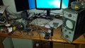
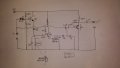
Hello people, it's been a while since i logged in this forum. I'm currently typing from my phone because my PC motherboard "accidentally" touched a bad ground from a USB mixer and blew out :D, here is the problem: i've worked for a few days with 3 high power PA systems and had to repair 3 times the HF compression drivers because the people behind the console were too busy to hear the pain coming from the speakers and left the volume way too high. The problem is that no matter how many time I get there and lower their volumes saying that the have to adjust it to the CD that's playing because they are recorded by other peoples and they have too much of dynamic range to blew speakers... I've spent some days burning transistors and stuff trying to build a simple audio compressor. It's made of one peak detector, a strange thing done with diodes that I don't know how it works but it does and lastly a simple class A Amp. Amy suggestion on how I can improve it? On the oscilloscope it doesn't seems so linear and compress only bass frequencies.. And yep I've burned out 4 germanium diodes so now I can't test anymore. Hope you understand my bad english :)
 

Attachments

Thread Starter

CRY&PRAY

Joined Jan 6, 2014
84
And hum that's why things blow easily :D have to clear up a bit before testing some more, in the meantime if we can work on the schematic before I blow other components
 

Attachments

Last edited:

Thread Starter

CRY&PRAY

Joined Jan 6, 2014
84
Luckily the speakers are not mine, they paid for them :D. That NE570 is perfect for me.. I don't know how to use it because I didn't found any application beside the data sheet test circuit and probably my "chip dealer" might not have it :( any other ideas? Thank you and to all the plp that will help me.
Edit 1: searching around a bit I've found this www.seekic.com/circuit_diagram/Audio_Circuit/60_db_Range_Compressor_For_Audio.html . it looks nice and I can get the parts quite easily. I have an lm358 and a lot of junk TV boards to scrap components, I might try it, just have to make it work on single rail.. We'll see tumorrow, good night
 
Last edited:

#12

Joined Nov 30, 2010
18,224
You can't refuse the, "perfect" chip because you haven't learned it yet. The app data is in an old Signetics book. I certainly hope it is on the Interwebs, somewhere!

Signetics, 1989 Linear Data Manual, Volume 1, Communications, page 4-341
 

Thread Starter

CRY&PRAY

Joined Jan 6, 2014
84
You can't refuse the, "perfect" chip because you haven't learned it yet. The app data is in an old Signetics book. I certainly hope it is on the Interwebs, somewhere!

Signetics, 1989 Linear Data Manual, Volume 1, Communications, page 4-341
I'm not refusing it, it seems simple to use: just place the right value of resistor or cap and it will do the rest. The problem is that I might not be able to get it so I'm searching something even more complicated but done with easy to find parts
 

Kermit2

Joined Feb 5, 2010
4,162
how is the speaker wired, specifically, what kind of crossover network is present? 90% of the amps power will/should be going to the bass. you can feed a horn tweeter with full spectrum audio and it will only reproduce high notes, but this will very quickly destroy them. If you aren't sure about your crossover then check on it.
 

#12

Joined Nov 30, 2010
18,224
I'm not refusing it, The problem is that I might not be able to get it
I already gave you a link where to buy it, but you have not told what country you are in. Am I to guess where you can buy parts?
I already guessed, and wrongly. :(
 

Thread Starter

CRY&PRAY

Joined Jan 6, 2014
84
I already gave you a link where to buy it, but you have not told what country you are in. Am I to guess where you can buy parts?
I already guessed, and wrongly. :(
My bad, I live in Italy and i'd like to get it working for Saturday and Sunday, pieces might not get here in time while my "ic dealer" could give me parts the same day. Getting late here, time to go to bed ;D
 

Thread Starter

CRY&PRAY

Joined Jan 6, 2014
84
how is the speaker wired, specifically, what kind of crossover network is present? 90% of the amps power will/should be going to the bass. you can feed a horn tweeter with full spectrum audio and it will only reproduce high notes, but this will very quickly destroy them. If you aren't sure about your crossover then check on it.
Crossovers are fine, I had to raise the xover point to fit the new HF horns and i've removed the bass winding so the woofer is seen like a full range and the HF gets less power in order to preserve them. The problem are the people behind the console, the have a 1500 w RMS amp hooked up to two 250 w 15" speakers, they have to play a ton o CD and each one is usually a mix of 2-3 songs with sometimes 6db of difference between, that causes them to turn up the volume when it's low but when it's too high they just don't care... Music peaks for 10 h no stop and you finish the day with blown horns, that's why i'm asking for a compressor so I can do the job that other people doing their CD had to do...


Edit: BTW the crossover is quite simple, one coil for the sub (that I've shorted) and a coil with 3 caps around for the HF, guessing it's a first or second order one (I could be wrong on the order). When I've opened the drivers the coin didn't shorted out immediately, it catch fire! There was a burn on the magnet going all the way out... Those horns are stressed too much...luckily I could sit near the operator for the entire day so I could control the volumes and the speakers managed to do their job just fine, Saturday I can't.. We have 3 systems in 3 different zones and I have to check the others
 
Last edited:

Thread Starter

CRY&PRAY

Joined Jan 6, 2014
84
Good morning, seems that the only option that I have right now it's to build this and hope to get a good amount of compression, I want them to try in vain raising the volume with no changes *evil*. Now the question, how can I make it works with single rail supply, it would be great a 12v, I see in the schematic it wants a +-5v so not a big deal and I plan to use an lm358 (I know it's dual, I'll be using it mono) http://www.seekic.com/circuit_diagram/Audio_Circuit/60_db_Range_Compressor_For_Audio.html I still have to learn how op amps works :D
 

Thread Starter

CRY&PRAY

Joined Jan 6, 2014
84
I've made this little peak detector, can I use it's output to drive something that short the audio to ground? Any suggestion? The transistor is a j13007 and the diode is 1n5393
 

Attachments

Last edited:

Kermit2

Joined Feb 5, 2010
4,162
the amp is the problem. It is to powerful for the speakers attached. Most pro-audio amps have input sensitivity adjustments. please check for this, and dial it down about 10-20 db.
 

Thread Starter

CRY&PRAY

Joined Jan 6, 2014
84
the amp is the problem. It is to powerful for the speakers attached. Most pro-audio amps have input sensitivity adjustments. please check for this, and dial it down about 10-20 db.
I did indeed limited the volume.. Thr problem is still the same, they need to have some sort of gain to boost the quite parts of the CDS... I need something to reduce this difference so I can limit the volume as I want to without having them to tell me that they can't boost the volume when it's too low and you can't hear any music...
 
Last edited:

Thread Starter

CRY&PRAY

Joined Jan 6, 2014
84
Well i've managed to get something to work, is basically my peak detector with two diodes in parallel. The peak detector has been modified a little with a pot so I can adjust the bias of transitor.. So far so good :D
 

Attachments

Thread Starter

CRY&PRAY

Joined Jan 6, 2014
84
Well, I've made it :D it works so nicely and you can turn that volume up as much as you want this circuit will rock you. Now it's done in the ghetto style, tomorrow I'll trace down the schematic and build it on the board, if you are interested i'll post the schematic. It uses 4 j13007 transistor, two of them are working in class a amp for the input (only for the peak detector) and output. I'm so happy that this thing works!
 

Attachments

Thread Starter

CRY&PRAY

Joined Jan 6, 2014
84
:D:DI'm currently running the circuit here and it's working perfectly, the face that they did when the volume dropped when it was too high​
 

Thread Starter

CRY&PRAY

Joined Jan 6, 2014
84
Of course I'll post the schematic, I had a little problem with the RATIO trimmer that should be a smaller, I suggest a 10 k, replace the 2.2uf with a 10 uf. The diodes are: d1 is normal 1n4007, d2 and d3 are two transistor-like diodes inside PC PSU. You may want to improve the first class A amp because if It distort it will compress distorting. It's running fine and it's doing great!. Any suggestion on how I can improve it is apreciated.
 

Attachments

Last edited:
Top