 Facebook
 Google
 GitHub
 Linkedin
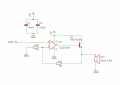
Hi i built a very simple audio amp-circuit for my little speaker.
i built it from another schematic i found.
but there is a problem of the sound quality of it, actually if i connect it to my smartphone and listen there is noise/distortion in the background of the music.
and if i connect it to my PC the sound quality is very good which i am satisfied with. i've recorded samples of it if you want to listen. https://drive.google.com/file/d/1E6YHDswBZBKyTp1XUo60Dz8H64Rfo84r/view
https://drive.google.com/file/d/1ZOXj2FkDy244TNFrhLZe43cbzIwtKrac/view
my questions are:
how could i reduce the noise if i plug in the smartphone ? some low-pass filter ?
in the idea-schematic why is there a PNP-BJT ? this circuit works with and without it.
is R1 really necessary ?
Attachments
-
 3.9 KB Views: 89
 -
 363.5 KB Views: 86


