Facebook
 Google
 GitHub
 Linkedin

The other day, while I was plotting brilliant ways to create brilliant works of electronics, the idea of making iPod speakers occurred to me. I found a broken pair of iPod earphones I had lying around, cut and stripped the wire, sanded of the enamel from the wires, and quickly found that speakers besides the iPod speakers worked fine, as well. After doing a quick victory dance, I found that the speakers played fairly quietly, while the iPod was at full volume. After some searching around online, I found that I would need to build a simple amplifier circuit, and that this had been done many times before.
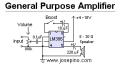
I bought a pair of LM386 semiconductor IC's from radioshack, plugged them, along with everything else I had salvaged from old equipment, and tested it out on a breadboard. The result was a distorted, muffled, sporadically loud amplifier. I gave up on the guide I had been using, and found this. http://josepino.com/?mini_amplifier_lm386 I would be using the "General Purpose Amplifier," the third diagram on that page.
If I can get this to work, i'll be making using a stereo potentiometer for the volume of both the left and right speakers.
As close as I am, a bit of that diagram confuses me to no end. At the far left, the volume control. As far as I can tell, it's a 100k potentiometer. In the diagram, two leads go in, and two come out. The third wire of the potentiometer seems to go to the capacitor, and then to pin 3 of the IC. But what about the second output? Should I attach wires from pins 2 and 4 of the IC to one of the outside wires of the potentiometer, as well as to the negative end of the battery?
I know this is long and confusing, but i'd love any help I can get. If you have any suggestions about the project in general, they'd be greatly appreciated. Thanks in advance
I bought a pair of LM386 semiconductor IC's from radioshack, plugged them, along with everything else I had salvaged from old equipment, and tested it out on a breadboard. The result was a distorted, muffled, sporadically loud amplifier. I gave up on the guide I had been using, and found this. http://josepino.com/?mini_amplifier_lm386 I would be using the "General Purpose Amplifier," the third diagram on that page.
If I can get this to work, i'll be making using a stereo potentiometer for the volume of both the left and right speakers.
As close as I am, a bit of that diagram confuses me to no end. At the far left, the volume control. As far as I can tell, it's a 100k potentiometer. In the diagram, two leads go in, and two come out. The third wire of the potentiometer seems to go to the capacitor, and then to pin 3 of the IC. But what about the second output? Should I attach wires from pins 2 and 4 of the IC to one of the outside wires of the potentiometer, as well as to the negative end of the battery?
I know this is long and confusing, but i'd love any help I can get. If you have any suggestions about the project in general, they'd be greatly appreciated. Thanks in advance