 Facebook
 Google
 GitHub
 Linkedin
Hi All,
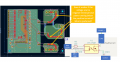
I'm designing a MCU controlled, 3 channels SSR output board.
I attached a snapshot of the layout & the relevant schematic symbols for this question:
Does it matter if there is copper pour of the negative source terminal under the positive source terminal?
The frequency is quite low, 500Hz for this case, so i guess it won't have big impact, if any impact at all.
Is it better to keep the layout like this? or avoid placing the copper pour under the positive terminals?
Also, should i place flyback diode for these SSRs?
Thank you,
Attachments
-
 363.5 KB Views: 3


