Facebook
 Google
 GitHub
 Linkedin
good day all,
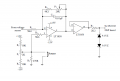
this is a circuit from a pdf which i am basing some of my design concepts on.
however there are a few things i dont understand!
for example:
1> how do i choose the correct op-amp?? (the sensor/transducer measures a peak value of 500V, and 5A from an induction motor). here the LT 1058 is used, and i have no idea why it is??
2>R1 and R2 --- i have no clue how to determine the resistor values here, i know that the board that this signal conditioning unit is connected to has a current max at its ADC input pins of ~10mA
3>shouldnt there be a cap in parallel with R7 in order to perform the operation of a low pass filter cutting out frequencies > 1/2 the nyquist freq?? instead the literature says that this is done by op-amp with (R6 +P2) and C1.
4>P2 (pot) is adjusted so that the max voltage to be measured (at signal conditioning input)gives max voltage of 10V (for the DSP board max voltage). this means that this forms an analogue divider circuit. so does this mean that instead of point 3> above R6 and C1 form the cut off freq.?? but then again adjsuting P2 would mean the knee point of the LPF changes to a higher/lower value (defeating the purpose of an LPF).. indirectly as we attempt to correlate max measured voltage to max DSP board input (of 10V).
please reply asap, this is important
Thanks team!
this is a circuit from a pdf which i am basing some of my design concepts on.
however there are a few things i dont understand!
for example:
1> how do i choose the correct op-amp?? (the sensor/transducer measures a peak value of 500V, and 5A from an induction motor). here the LT 1058 is used, and i have no idea why it is??
2>R1 and R2 --- i have no clue how to determine the resistor values here, i know that the board that this signal conditioning unit is connected to has a current max at its ADC input pins of ~10mA
3>shouldnt there be a cap in parallel with R7 in order to perform the operation of a low pass filter cutting out frequencies > 1/2 the nyquist freq?? instead the literature says that this is done by op-amp with (R6 +P2) and C1.
4>P2 (pot) is adjusted so that the max voltage to be measured (at signal conditioning input)gives max voltage of 10V (for the DSP board max voltage). this means that this forms an analogue divider circuit. so does this mean that instead of point 3> above R6 and C1 form the cut off freq.?? but then again adjsuting P2 would mean the knee point of the LPF changes to a higher/lower value (defeating the purpose of an LPF).. indirectly as we attempt to correlate max measured voltage to max DSP board input (of 10V).
please reply asap, this is important
Thanks team!
Attachments
-
 33.8 KB Views: 87