Hi.
Can someone explain the way this power supply works ?
There is +120V instead of +220V as supposed at D1101 cathode. D1101 and C1101 replaced. AC is OK.
All other voltages are fine. Horizontal sweep is narrow, half the screen width.
If the +120V is very low (20V?) then first check the +8V and -8V supplies as these are the references for the +120V supply regulator.
If these are OK, is TR1102 getting hot? If it is then the problem is likely to be that the +120V supply is overloaded. If it is cool then the problem is in likely in the regulator circuit.
Thank you.
Reference taken from common chassis ground. D1101 cathode is +95V to ground, supposed to be +220V referenced to ground.
P1105 terminals have solid perfect values, no ripple and supply all the oscilloscope circuits . Only +220V (not labeled on first schematic) is faulty.
R1101 is 100K
Across C1101 there is minus 25V !
TR1102 is barely warm, like 50C. Checked its junctions, OK at 0.6V.
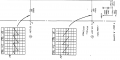
Previous schematic was from user manual, this, same section, from service manual :
Can you determine if there is a connection from P1101 pin 1 to the anode of D1101?
And is there an AC voltage in the anode?
Maybe the "JP" is off or faulty?
Confirmed continuity 0.1 ohms P1101-1 to anode of D1101.
100.1VAC at D1101 anode respect to chassis common ground.
168VAC between brown and yellow secondary.
132VAC between red and yellow secondary.
36VAC between brown and red secondary.
Just in case:
You cannot check those diodes while still in the circuit because of the very low resistance of the transformer. You must at least lift one end of each diode to check them.
Applied 12V to removed original C1101 and retained charge to a couple of minutes later, as my capacitance meter goes only to 20μF. Replaced anyway with 400V rated one.
Not removed C1102 shows 170V across and little 7.8V ripple. Removal would mean risking like 20 tiny connectors and front panel nuts to pull the board out, which will not allow to put to work and probe when removed. Waiting as last resource to do it.
Thanks. I will try to extract the horizontal section magnified from the .pdf
Seems I cannot. The file shows a padlock with its icon, and unable to capture the page and paste here. Retrying with unstitched screenshots... I cannot even put this text on top of the 4 images that make the page.
The bottom image did not take... retrying in next post.
Thanks, Mr. Chips for a decent schematic.
Voltage across fusible resistor R859 is 1.5V (not blown)
Did not find +220V on the vertical amplifier. Uses +120V.
 Facebook
 Google
 GitHub
 Linkedin