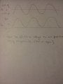
I want to take a 2.5 V P-P signal and shift it so that all of it is above the 0 line. Basically have it read 0 to 5 volts . Would that be a precision Rectifier? How would you suggest I approach this? Thanks.
Attachments
-
741.8 KB Views: 18
That helps explain your objected, but doesn't answer the question I asked. You mentioned using a precision rectifier. Would using a precision rectifier accomplish what you want? If not, why not?I took a 5 V p-p signal, ran it through an inverting amplifier to cut the signal down to 2.5 V P-P, then I used a 5 k and a 10k resistor to level shift the signal to get it to 3.3 V P-P. Now I want to look at the whole sinusoid but I need it all above the 0 axis. I plan to send a 3.3 Volt signal to an ADC. SEE BELOW.
60 HZFrequency becomes important.
What is the frequency of the input signal?
Ok, that is not bad. Just about any common transistor can handle that.60 HZ
I'm not sure. I don't think that will do the job. I think the diode is what takes care of that but Im a little torn on whether I should use a half or full wave rectifier here.That helps explain your objected, but doesn't answer the question I asked. You mentioned using a precision rectifier. Would using a precision rectifier accomplish what you want? If not, why not?
Mathematically, what do you want your output signal to be in terms of your input signal?
this is for an industrial application so I would think it might come in contact with harmonics.Ok, that is not bad. Just about any common transistor can handle that.
But will any king of rectifier do what you want?I'm not sure. I don't think that will do the job. I think the diode is what takes care of that but Im a little torn on whether I should use a half or full wave rectifier here.
A half wave rectified waveform is going to only show the positive portion of the wave right? If I used a full wave rectifier, that would basically take the negative half and invert it to make it positive ( so the signal would be closer to DC type waveform). That would seem to be not a good thing since we are inverting half the signal. Seems like I would need the half wave. We are only getting the positive half. I was thinking initially we would need to shift the whole wave form up but I realize now I cant do that because AC has a + and - component. So, I would only want the half wave I'm using now, I think.But will any king of rectifier do what you want?
Sketch your waveform that goes both above and below the axis. Now sketch what that waveform would look like it if it rectified. Is that what you want?
Why can't you shift the whole wave up?a half wave rectified waveform is going to only show the positive portion of the wave right? If I used a full wave rectifier, that would basically take the negative half and invert it to make it positive. That would seem to be not a good thing since we are inverting half the signal. Seems like I would need the half wave. We are only getting the positive half. I was thinking initially we would need to shift the whole wave from up but I realize now I cant do that. So, I would only want the half wave I'm using now, I think.
What information are you trying to get out of this signal?Unless, I can make a general assumption that the negative and positive values are going to be the same. So, once flipped up to the top I can use them to make the signal more like a DC value. Then, with a capacitor, I can make the signal similar to a DC signal. For current sensing is the a flawed way to approach it?
I'm not sure how to shift the voltage waveform up without rectification.Why can't you shift the whole wave up?
Again, what is the mathematical relationship you want between the input signal and the output signal?
What information are you trying to get out of this signal?
Again. What is the mathematical relationship between the signal you have and the signal you want?I'm not sure how to shift the voltage waveform up without rectification.
I have an input of 0-70A, that through a CCVS will convert to 0-20mA. The 0-20mA outputs a 0-5V value (which is again stepped down to --3.3 V so as not to burn up the ADC. The ratio through the CCVS is 1/1000. Then the level shifting resistor arraignment converts from 5V to 3.3 Volts.
I'm trying to get a signal that is 0-3.3 Volts with very low current draw.
1:1. I was thinking of using a level shifter but I think it only reduces or expands a voltage magnitude. Initially I thought I could use it to move a sin wave positive or negative.Again. What is the mathematical relationship between the signal you have and the signal you want?
Your original post had a drawing that showed a sinusoidal signal (at least roughly) that was 5Vpp centered on zero. So let's call that v_in(t).
v_in(t) = (2.5 V)·sin(wt)
You now want to put that into a black box circuit and get out the signal (let's call it v_out(t)) at the bottom of that drawing.
What is the mathematical relationship between v_in(t) and v_out(t).
Hint: There's a reason why you used the word "shift" in your title and original post.
This is the Homework Forum. Simply giving answers denies the OP the benefit of learning how to solve the problem with some guidance...This might help: http://www.daycounter.com/Circuits/OpAmp-Level-Shifter/OpAmp-Level-Shifter.phtml
The only thing I don't like is the fact that they don't say which op amp they are using. It seems to be some kind of rail to rail single supply op amp.
Are you sure OP is doing homework?This is the Homework Forum. Simply giving answers denies the OP the benefit of learning how to solve the problem with some guidance...