Shelly plus 1 to control 110vac winch with dc motor

Thread Starter

Slickem

Joined Dec 6, 2024
3
I searched for something similar and couldn’t find anything and hope I didn’t over look it.
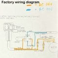
So I have a 110vac winch that controls my bifold garage door (airplane hanger type that folds horizontal). It has two rocker switches to control the winch now. I’m wanting to put two Shelly plus 1 smart switches in the circuit and take out the rocker switches. I have a upper and lower limit switch wired into the rocker switches now and will have to figure out where to wire them in the circuit once I get the Shelly’s wired into here is the factory working diagram from the strong arm 12000ac winch, wiring diagram I made that I think would be correct to make it work.
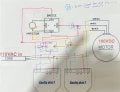
im hoping to get some feedback back on my diagram to know if it will work or what suggestions others may have to make it work idk if my diagram won’t. Also if someone could help me with where to put the limit switches in my new diagram would be helpful as well.
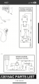
I added another bridge to the circuit from the company so I would have two exact bridges that is in the winch now. I attached a picture of the model nimb r for it as well.
Any input would be greatly appreciated! And I’m sure I could buy a different 110vac winch that would work better but this winch is what I had laying around at the time.
 

Attachments

Thread Starter

Slickem

Joined Dec 6, 2024
3
Welcome to AAC.

You probably want a Shelly 2, not 1.
Why the Shelly 2 vs the Shelly plus 1? I have two Shelly plus 1’s. What’s the benefit to using the Shelly 2? What model of the Shelly 2 would you recommend and do you have a wiring diagram that you could share with me on how to wire it with the Shelly 2 you are talking about. Honestly just wondering as I’m not sure the best route to go with it.
 

Ya’akov

Joined Jan 27, 2019
10,226
The Shelly 2PM is specifically designed to hande bidirectional motor control. The wiring diagram is on the the device itself.
 

MisterBill2

Joined Jan 23, 2018
27,182
I am having a difficult time seeing how your wiring diagram can work. At best it appears that it would only run the motor in one direction. I see three different wiring diagrams and only one of them is anywhere near showing the whole arrangement.
How am I supposed to evaluate a system to see if it can work when part of it is not shown??? I can make a guess but it would look a lot like what I would do, which may not be at all what the TS is thinking.
I see extra diodes penciled in to avoid having one massive short circuit, and while the extra diodes will avoid the short circuit they will also avoid any operation.
I am not at all familiar with a "Shelly1" or a "Shelly 2", but based on the comment by "Y" i am guessing that they are some sort of remote control device. WHICH WE ARE NOT SHOWN. Certainly there is some way that such a device could be utilized, but since I get no description of what the "Shelly" devices are or what they do, I am not going to present that scheme now.

AND, initially the motor was described as ab AC motor, but in the drawings it is shown as a 100 volt DC motor. The two kinds are controlled in quite different manners.
 

MisterBill2

Joined Jan 23, 2018
27,182
I don't see the need for two rectifier supplies, especially when you show two relays??
Even more important, Max, is that if it is an AC motor, as stated in post #1, how is it going to work with a DC supply???. I have observed that many winch motors are DC motors, so it has me a bit confused. Which is it, really???
 

MaxHeadRoom

Joined Jul 18, 2013
30,561
Even more important, Max, is that if it is an AC motor, as stated in post #1, how is it going to work with a DC supply???. I have observed that many winch motors are DC motors, so it has me a bit confused. Which is it, really???
I don't see an AC motor mentioned in #1, I believe it was implied to be AC SUPPLIED winch using a DC motor. i.e. 110vac Winch. :(
 

MisterBill2

Joined Jan 23, 2018
27,182
OK,Max, As I look back I see you are correct. "AC supplied" and later he mentions an internal bridge. I lost that part. THAT is what the well drawn circuit diagram is showing!
I see the limit switches in the other drawing but that does not seem to make any sense the way it looks like they are connected. So possibly a "shelly1"controlling a relay for up and another controlling a relay for down can be made to work.
Certainly you or I could do it easily. Describing how it should be done is a different task.
 

Thread Starter

Slickem

Joined Dec 6, 2024
3
I don't see the need for two rectifier supplies, especially when you show two relays??

I’m a welder not an electrician lol please bear with me as I try to answer and describe the questions you had! By the way thanks for the reply’s. I hope I can learn from you all!

——Short run down of the factory wiring explained —— So cord of the winch plugs into my wall 110v AC then to a bridge rectifier (changes from AC to DC), runs to the switch (from bridge to switch it’s dc), then runs from the switch to the motor (the switch changes the direction of the motor,again 100vDC).

——what works in my head as a way to wire it that would work——
My thought is to change it to plug into my wall plug (110vAC),then run ac current to the Shelly 1 or 2 (because they can’t handle 100vDC I will just run AC to them since they are rated for the ac amps and volts), then from the Shelly device (which is just a WiFi smart switch controlled by a app to be able to remotely control a electrical device) to a bridge (to change the AC to DC), then to the motor. The two bridges to wire to the motor the opposite way from each other thinking that will change the direction. The diodes will keep the flow from back feeding into the other bridge.

Now this makes sense to me but as I’m not a master of electrical circuits I’m asking if this would work really.

There isn’t two relays. I think you are thinking the Shelly smart switches are relays but they aren’t. They are powered by a supply(110vac in my situation, or can be 12vdc powered as well) and you hook the incoming load wire to the Shelly device and when it gets the signal from your pushing the button on the app you “switch” it, then it just connects the load wire that’s incoming and out going together that then goes to the electrical device you are wanting to control. Like a on off latching or momentary switch is all it is that hooks up to WiFi and has a few extra feathers as power consumption or some Shelly devices can set limits like how long it runs before it stops once you push the button in the app that controls the Shelly device

the winch has no relays now from my understanding looking at the drawings from the companies website. I don’t understand why I have been told I needed two coil relays 100vdc 16amp spdt (which I haven’t been able to locate any where myself as of yet and I even called the local electrical motor rebuilding business and they said they didn’t think I could get anything to those exact specs but they didn’t deal directly in them but more rebuilding the electrical motors).

my understanding is if you take and swap the wires on the DC motor it will run in opposite directions (this is what I have studied on “how DC motors work” on YouTube). So in my mind you wire the bridge where one would supply the motor wired one way and then the opposite the other way to reverse it it should work. But then again this is a $800 winch I don’t want to smoke if this isn’t a way to do it.
im getting rid of the rocker switch when I add the Shelly smart switches to the circuit.
I would add diodes to keep the electrical flow from back feeding into the other bridge when the one Shelly smart switches is activated via the Shelly app.
OK,Max, As I look back I see you are correct. "AC supplied" and later he mentions an internal bridge. I lost that part. THAT is what the well drawn circuit diagram is showing!
I see the limit switches in the other drawing but that does not seem to make any sense the way it looks like they are connected. So possibly a "shelly1"controlling a relay for up and another controlling a relay for down can be made to work.
Certainly you or I could do it easily. Describing how it should be done is a different task.
it’s funny you say the 1 well drawn diagram when two of the diagrams are exactly the same I just highlighted one with the ac and dc current flow. The two diagrams that are in the same picture are the same winch but one has a hand held control switch box and the other one only has a switch on the winch itself. So technically three of the electrical diagrams are actually well drawn up and have nothing left out as they are off the companies website and they sell the winches wired that way. Seems you get mad you miss read my post. I’m just a hobbiest diy guy who is interested in electrical circuits now and wanted to tackle this myself. Like above I don’t want to smoke this $800 winch hen I plug it in so I came here to ask if my idea in my head that makes sense to me would work or not and if not I would like to know why so I can better understand this type of electrical circuits.
you couldn’t draw me up a quick sketch to show me how “it should be done” since you can’t describe it?
I’m just here to learn from people who know how it should be done properly if they are willing to share their knowledge with me. I may ask why it should be done that way to understand it. Maybe this all clears ip some of y’all’s questions and concerns. I appreciate the responses and hopefully.
 
Top