I tried to use the same supply for a microcontroller and rc servo once. But when the servo moved, the powersupply couldn't handle the sudden current draw, even with a 1000µF cap, and the voltage dropped so the brown-out detection in the microcontrolled tripped and reset the micro.
The capacity of the supply could be sufficient, but the initial resistance of the motor presented to the supply at full power in is very low.
Therefore the motor should be switched with a buffer transistor or semiconductor of some kind, you normally never switch a load such as a motor from a PIC output!!
Bad design!
Max.
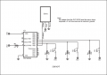
You can run them from the same supply but route the power to the servo on its own trace. Join that trace with the PIC power trace right at the regulator with heavy decoupling. Decouple the PIC right at the PIC package as well. Route the grounds separately as well, joining them at the regulator's ground pin. The key is not to share the conductors with their attendant voltage drops, noise. The decoupling at the regulator pins as well as the regulator capacity and unregulated supply all need to be sufficient to keep the common points at a steady +5V.
The IO line from the PIC is not a switch, its a PWM output that determines the servo position. That said, I don't recall what its current requirements are but they are within the PIC's range.
Since the IO is likely to be noisy, the midrange PIC should have its IO shadowed (no bcf, bsf on the PORTs).
I've run many RC servos with just such a setup but you have to pay attention to the power distribution and be sure that the supply has enough oomph to drive the servo under load.
You can also run the servo off its own regulator if you like.
Separate power supplies might be nice, but I don't think you need them as long as you have a single power supply that can handle the maximum current, and the PIC and the servo are decoupled appropriately. I think the recommendation for separate power supplies and the brownout experience are more due to layout and decoupling issues, and possibly an underspec'ed 5V supply.
Also, if I recall typical servos, the white lead is just a PWM signal, so the PIC is not driving the servo motor load. If that's the case, I think the design is fine connecting that MCU pin directly to the servo signal input.
Another way to minimize momentary drops at the PIC is to add a small resistor in series with the power inserted before a large decoupling capacitor to the PIC power pin. The resistor must be sized to drop perhaps only a couple tenths of a volt for the normal current draw of the PIC.
 Facebook
 Google
 GitHub
 Linkedin
 20.7 KB Views: 34


