Sequential Circuit --> State Machine Diagram

Thread Starter

wazzizit

Joined Jan 14, 2015
19
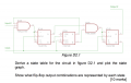
Hi, I was hoping someone would be able to help me with the question attached. I know the steps to be:
Determine flipflop input equations and output equations; derive next state equation; plot next-state map for each flipflop and outputs; combine these to a state table; plot a state graph. I'm stuck on the first step! All help appreciated!!

Thanks,
A
 

Attachments

MikeML

Joined Oct 2, 2009
5,444
I'll get you started: Label the three flip-flops X, Y, Z.

The expression for Dy=~X (read it as NotX).

You write Jx, Kx, Jz and Kz
 

Thread Starter

wazzizit

Joined Jan 14, 2015
19
Well the output from the AND gate feeds Jx and Kx thus Jx=Kx, but with notX from the Dtype as you said, X and notQ from Z, i'm really struggling to compute what the input equation would be; surly it can't be X.notX.notQ?
 

WBahn

Joined Mar 31, 2012
29,932
As you said, the first step is to determine the flip-flop input equations. You have three flip-flops, two JK and one D, so you have a total of five input equations. What are they? Express each in terms of the outputs of the other flip-flops and/or the inputs to the circuit as a whole.
 

Thread Starter

wazzizit

Joined Jan 14, 2015
19
Jx=Kx=yQ.X.zQ' and Jz=Kz=yQ.xQ` is four of them and Dy=X' is the other? Where lower case letters are flip-flops and upper case X is the input, and Q represents the output from that block and Q' being Qnot.
 

WBahn

Joined Mar 31, 2012
29,932
Jx=Kx=yQ.X.zQ' and Jz=Kz=yQ.xQ` is four of them and Dy=X' is the other? Where lower case letters are flip-flops and upper case X is the input, and Q represents the output from that block and Q' being Qnot.
I'd recommend using a consistent nomenclature. You use Jx (signal name followed by FF id) and xQ (FFid followed by signal name). Pick one. Let's use the former since that has the feel of a signal name with a subscript. Also, using upper case X for something that is unrelated to the lower case x can lead to confusion, particular if handwritten since both letters have the same form. But we can deal with that okay.

I agree that Jx=Kx=(X)(Qy)(Qz') but I don't agree with the other two. You day that Dy=X', meaning that the input to the FFy is the inverse of the input signal. See what I mean about using the same letter for two different things? You also need to be more explicit in working out the expression for Jz=Kz. I think you applied DeMorgan's incorrectly.
 

MikeML

Joined Oct 2, 2009
5,444
When I do this, I use lower case x, y, z as subscripts, e.g. for Jx, Dy, etc.

I use upper case X, Y, Z as the Q outputs of the flip-flops. X', Y', Z' or ~X, ~Y, ~Z would be the Q-bar outputs. I suppose you could also use Qx, Qy, Qz and Qx', Qy', and Qz'.

The External input "InputX" is problematic, because we have already said that X is the Q of a ff, so lets call it Ix, which cannot be confused with Jx, Kx, Sx, Rx, etc.
 

Thread Starter

wazzizit

Joined Jan 14, 2015
19
I'm not sure what I did wrong, this is the only step of the problem that I am having massive difficulties with. My examination is tomorrow and I would be eternally grateful for some guidance as to how to find the input and output equations of FFs from circuit diagrams.
 

WBahn

Joined Mar 31, 2012
29,932
The input to the Jz and Kz is from the output of a NAND gate, correct?

So that means that Jz and Kz are equal to NOT (A and B) or (A.B)'. If you apply DeMorgan's to this, you get (A'+B')'.
 
Top