 Facebook
 Google
 GitHub
 Linkedin
My college homework ask me to design a simplified traffic light controller that switches the lights at a street intersection (North-South street N-S and East-West street E-O). The controller's input is a button called **PASS**, which is activated by pedestrians when they wish to cross one of the streets.
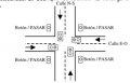
As it can show in the following graphic:
The controller outputs two signals, **N-S** and **E-O**, where a value of **0** indicates a **red light** and a value of **1** indicates a **green light**.
- If there are no pedestrians, **N-S = 0** and **E-O = 1** for **1 minute**, then the lights switch to **N-S = 1** and **E-O = 0** for another **1 minute**, repeating this cycle.
- When the **PASS** button is pressed, **both N-S and E-O turn red (0) for 1 minute**, provided that the current green light phase has completed. After this pedestrian crossing phase, the N-S and E-O signals continue alternating as before.
### Requirements:
**A)** Develop a state diagram and a state/output table.
**B)** Encode the states.
**C)** Obtain the associated logic circuit.
What I want to know is how many states the problem should have, considering that it’s not only the traffic light colors that change with the 1-minute timer, but also that they are activated by the push button.
Second, how the transitions should be if the states were controlled by a monostable triggered on a rising edge.
A brief textual description is enough for me; no need to do anything else.
Attachments
-
 34.3 KB Views: 1


