 Facebook
 Google
 GitHub
 Linkedin
Hello,
i would like to design a SEPIC(or buck-boost) converter which converts an input voltage with range 3-19V to 8.4V. On its output will be connected three DC-DC converters which are depicted below :


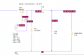
My first try was this (components calculated according to some articles i found), but cannot convert input voltages under about 8V:

Could anyone suggest how to calculate the components of the SEPIC(or buck-boost) converter?
The complete circuit :

i would like to design a SEPIC(or buck-boost) converter which converts an input voltage with range 3-19V to 8.4V. On its output will be connected three DC-DC converters which are depicted below :
My first try was this (components calculated according to some articles i found), but cannot convert input voltages under about 8V:
Could anyone suggest how to calculate the components of the SEPIC(or buck-boost) converter?
The complete circuit :
Attachments
-
 13.2 KB Views: 4


