Perfect, thank you very much. Tt seems to work reaching 8.4 V for PW of 2.1u. Do you maybe know which component values should i change to reduce voltage ripple on output?
hi Peter,
I hope you have noted the Gate drive voltage on the sim post #43 has been increased in order to highlight the insufficient Gate drive voltage for the original MOSFET.?
The problem is that the 5V Vgate is not switching the MOSFET hard ON.
If you can find a suitable MOS that will be switched fully On with a 5V Gate voltage, it should help with the Vout problem
As Ron points out, you have high current levels in some components.
Hi ericgibbs,
to be honest i didint notice that you increased the gate drive voltage. I thought that replacing transistor irf540n with irf7413 makes the cicrcuit operate even with 5V gate drive voltage. I also simulated with 5V gate drive and it run properly. That's my last simulated circuit .
Peter523,
You can use one more, independent, self-oscillating converter
specially to provide 12V for PWM's of all your converters.
for example: Pololu 12V Step-Up/Step-Down Voltage Regulator S18V20F12
Vin=2.9V to 32V
Vout=12V
Iout=up to 2A
The ENABLE pin can be used to reduce the quiescent current to well under 1 mA. ADDED:
Or maybe he can use a logic-level MOSFET.
5.1W seems like a lot of dissipation for a 0.7mΩ MOSFET - is it all switching losses?
If so, probably a MOSFET with a smaller die (higher Rds(on)) would have less loss?
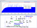
Sorry i may wasnt clear. The SEPIC i posted on post #47 had on its output the three DC-DC converters and it reached the desired voltage on its output (8.4V) with gate drive voltage of 5V. That's why i think problem is solved
Sorry i may wasnt clear. The SEPIC i posted on post #47 had on its output the three DC-DC converters and it reached the desired voltage on its output (8.4V) with gate drive voltage of 5V. That's why i think problem is solved
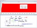
Circuit #47 has 7.4 V on its OUT.
Transistor dissipates 86,7 W of power:
============================================================================================================================ ADDED:
For example, how it can work:
 Facebook
 Google
 GitHub
 Linkedin