Sensitive Analog and Power Switching?

Thread Starter

scubasteve_911

Joined Dec 27, 2007
1,203
Hi all!,

I am looking for any tips or tricks on isolating noise from some power switches from the current sense portion of my circuit.

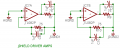
I already laid out a simple test board for my project, below is a portion of it. I believe I might have made a mistake by having the output at P2 run across the current sensing resistors R5 and R6. I am getting quite a bit of switching noise present on the output of the sensing resistors. There didn't seem a very elegant way to do this.

This isn't a big deal right now, but I will be laying out the final board soon. I will have 6-layers to work with, so I am hoping that might help with noise isolation. Can anyone offer tips about how to do this? I was thinking of soldering thick gauge wire to the PCB track to minimize inductance on the switching power lines. I'm trying to think of a good way to do it with more layers.

I am planning on operating this circuit from 50KHz to 100KHz and it will be putting out 2.8A rms max.

Any suggests would be welcomed, thank you!

Stephen
 

SgtWookie

Joined Jul 17, 2007
22,230
Hmm - digital, high-power switching, and low-level analog.

You Tube has most appropriate advice for this situation:
http://ca.youtube.com/watch?v=yJQFf0qj9Nk

Otherwise, it'll bite you every time.
Vsource and grounds for the above types - isolate them. Even a straight piece of wire has SOME resistance, and that will become a voltage drop, particularly at high power levels.
 

eeboy

Joined Sep 27, 2007
90
Yeah... what he said (SgtWookie)! Keep the analog as far away from the digital as possible.

The internal planes will reduce the impedance significantly and so you should see a noise reduction simply from that. Another thing I like to do is "stitch" the planes together using some bypass caps (in addition to the bypass caps you should have at each IC). I locate them based on the physical construction of the board. I normally try to get a stitch in every square inch or so. Also, make sure you choose the bypass caps appropriately based on your 50-100kHz switching frequency. I normally utilize a minumum of two decoupling caps... one .1uF and the other chosen to self resonate at the desired frequency (50-100kHz in your case).
 

Thread Starter

scubasteve_911

Joined Dec 27, 2007
1,203
Thank you for your replies, I appreciate the advice. I realize that I made a mistake on the PCB, I intended to not attach the input ground to the plane. Only through a high impedance connection anyways, or through a ferrite.

I'm a bit confused about the notion of bypass caps 'stitching' together planes. Can someone explain this? I believe I have heard of ferrite use for this, but definitely not capacitors. Don't you want to increase impedance to high frequency, not the opposite?

You definitely raise a solid point of choosing the capacitor to self-resonate, which gives the lowest possible power supply impedance :)

Any other pointers? I understand the 'keep em' separated' recommendation and have followed it, but isn't there a point where running the analog signal to great length will allow it more prone to noise injection?

Steve
 

eeboy

Joined Sep 27, 2007
90
The "stitching" I was referring to is pretty much doing the same thing the bypass caps do. They provide a low impedance path to ground for noise/transients.

Yeah... definitely! It's always a struggle. The optimum layout for noise is NEVER the optimum layout for connectors and such. Certainly having longer traces on your analog signals makes them more susceptible to noise... but then again if your digital signal traces become longer, the inductance increases compounding your problems.

I usually use ferrites just beyond the power input. These reject the high frequency noise (Xl increases with frequency).

I am by no means an expert in PCB layout... just sharing some tips from my experience.
 

Thread Starter

scubasteve_911

Joined Dec 27, 2007
1,203
eeboy,

Thank you again for your input. I am still very confused about the stitch capacitors. So, they allow high frequencies to pass between ground planes, but isolate low frequency transients or possibly DC offsets? Wouldn't you want to do the exact opposite? If you wanted a low-impedance path, then a direct connection would seem appropriate, even though it isn't a frequency dependent connection.

Yes, the longer the trace, the higher the inductance, the higher the mutual inductance if in close proximity to switching traces. I like the useage of ferrites, they make excellent filters. I am investing a lot of time and money into this PCB and wouldn't want to make silly mistakes rendering it with low-performance or worst case unusable.

Steve
 

eeboy

Joined Sep 27, 2007
90
I may be misunderstanding something... It's easier to comment when you know the purpose of the circuitry and the environment in which it will operate. For example, I just created a really simple control board (uC with 6 channels of ADC, along with some control of solenoids/motors). The circuitry is dirt simple but then you have to consider the environment in which it operates. This board is immersed in RFI as it sits next to a 300W RF Generator. Seventy percent of the components on the board are used to mitigate RFI and ESD.

Yes, the stitch capacitors provide a low impedance path for high frequency components. These capacitors are fixed between VCC (power plane) and GND (ground plane).

I am getting a bit of topic from your original post... your problem seems to be focused on the switching noise present in your current sense circuitry. Do you have any analog filtering on that particular signal? If so is where is it located? How do you use the current sense signal? Is it fed back into a switching controller? To an ADC? To a comparator?
 

Thread Starter

scubasteve_911

Joined Dec 27, 2007
1,203
eeboy,

Thanks again, I appreciate your input.

Now that makes sense, the use of capacitors stitching localized planes. I was thinking that you were connecting GND planes with capacitors and was failing to see the logic.

I am creating a self-sensing active magnetic bearing system. It is absolutely critical that I have highly intelligible current feedback, free of as much noise as possible. I am using a differential arrangement of sense resistors that is being fed into an instrumentation amplifier. This differential arrangement allows current to be measured during slow-decay mode, but needs to have a dynamic gain adjustment in order not to read double the current.

The instrumentation amplifier's signal is output to a 16-bit ADC. The ADC is directly interfaced with an FPGA, which will incorporate digital filtering. I will be LPFing one path of the signal for control, the other will be used for rotor position estimation.

I'm reading through an appnote for the L6205, which seems decent. As you had suggested, capacitor selection is extremely important. Besides value, ESR, lead inductance, and RMS current handling are important considerations. I botched the layout on the test board, so I hope to come up with something better for the final PCB. I will post it before sending it out, since it is going to cost $$$!

Steve
 

SgtWookie

Joined Jul 17, 2007
22,230
Something else you can consider is using an op amp to drive shield planes for your noise-sensitive analog signals. Getting deeper into it, I suggest you design your board so that your analog signals have a 50 Ohm impedance, just like a coax might. 50 Ohms is a decent compromise between transmit and received signals. Trace width vs proximity to the shield planes vs the dielectric constant of the board material all figure in. Using FR-4 material? Multiple layers cost beacoup bucks, but for lowest noise and a good impedance match, it can be worth it if you plan correctly.

The nice thing about using op amps for driving your shield ground planes is that the reference ground is unaffected if you're using JFET input op amps. Decent op amps have a high rejection ratio of power supply noise (up to 120dB) and with a decent design for an active shield driver, you can get the noise on your shield planes much lower than if you used passive planes.

Attached is a portion of a schematic I made up to drive a couple of shields for 75 Ohm video signals in a high-noise environment. The TL082 op amp certainly isn't cutting edge, but worse choices abound.
 

Attachments

Top