sensitive ammeter problem

Thread Starter

qitara

Joined Jan 18, 2013
112
Hi

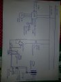
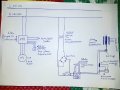
For a hobby project i am working on, i needed a meter that could do both DC volt and current measurements, i found a panel mounted meter that has what i need, i bought 4 of them (details of the meter in the link below), it works fine but has this problem where it is extremely sensitive to noise, it uses a shunt resistor to measure dc current. after installing it in a control panel which has other device inside one of them being a small 1,5KW VFD, i got this problem, as soon as i switch on the VFD the meter goes in a restart loop as if the power where being connected and disconnected (power source is isolated from the VFD) after multiple attempts trying fix this by changing all the meter circuit wires to shielded cables and grounding with no success, i uninstalled the meter and tested it using my bench power supply, it runs fine but... if i touch one of the 2 shunt resistor inputs on the meter with my finger it starts to do the same thing it goes ON and OFF... I tried the other 3 that i got, they act the same exact way, so recon it has to do with the way they where designed. my question is.... if this is noise related is there a way to solve this ?


https://www.aliexpress.com/item/DC-...a4b8-4406-a3fa-7b1eb46b7859&priceBeautifyAB=0


Thanks in advance
 

Tonyr1084

Joined Sep 24, 2015
7,905
This sounds like a problem way over my head. So all I have to offer is the possibility that your power supply isn't big enough to carry the current needed for all these devices. You could be seeing oscillation due to low power availability. But like I said, this is over my head.
 

Marley

Joined Apr 4, 2016
502
The VFD outputs a switched (chopped) waveform not a continuous current so is extremely noisy. You are always going to have trouble using the type of meter you have bought.

It would be possible to fit some filtering in the wires between the shunt and the meter.
How is the meter powered? This power supply needs to be completely isolated from everything else.

I would give up on the idea to use the same meter to measure both current and voltage.

Does the VFD produce an analog output proportional to motor current? Is there a serial data port that can be configured?
 

Jonlate

Joined Dec 21, 2017
118
I have a similar problem on Monday’s, I am very sensitive to noise! It seems to wear off during the day though.
As for your meter, sorry I can’t help!!
 

crutschow

Joined Mar 14, 2008
34,470
As Marley noted you might try an RC filter at the inputs to the meter.
Add a resistor (say 10kΩ) in series with each input and a capacitor (say 10μF) between the inputs.
 

Thread Starter

qitara

Joined Jan 18, 2013
112
I drew this simple drawing to make thing easier for you guys.

We can assume the circuit in the panel is causing the problem on the meter... as i mentioned i took the meter and the shunt resistor out of the panel and ran it using my bench power supply which can supply up to 60V/30A... it ran fine but if i connect long wires or even touch one of the meter resistor input it starts to do the reset loop thing ( this is outside the panel ). if i disconnect the shunt wires it runs fine and even inside the panel while the VFD is running but in that case i am only able to get voltage readings and not current reading.
 

Attachments

Tonyr1084

Joined Sep 24, 2015
7,905
A little sketchy on your description of how you're testing. You say everything works fine without the ammeter in the circuit. But when you try to put the ammeter back in the whole thing becomes unstable. Even if you put the ammeter outside in the garage and run really really long wires, as soon as you touch something it begins to flutter. At least (though I exaggerated a bit) I think I'm understanding how you're approaching this.

My concern is how the meter is powered. A drain on the circuit can drop the voltage in the meter and cause it to flutter as you describe. I'm thinking you need a more dedicated power supply after the rectified 40 volts (which when rectified and filtered will give you a max voltage of over 56 volts. Your meter - can it take that high an input? I'm thinking the meter power should be taken from before the PWM. OR maybe a separate PWM. That's where I'd start experimenting first. Find an isolated power source for your meter and see if you still run into the same issue. If you do then it isolates the problem as NOT being caused by a shared power source.

[edit] Crutschow beat me to the punch. I lightened and rotated the photo too.
 

Attachments

Thread Starter

qitara

Joined Jan 18, 2013
112
A little sketchy on your description of how you're testing. You say everything works fine without the ammeter in the circuit. But when you try to put the ammeter back in the whole thing becomes unstable. Even if you put the ammeter outside in the garage and run really really long wires, as soon as you touch something it begins to flutter. At least (though I exaggerated a bit) I think I'm understanding how you're approaching this.

My concern is how the meter is powered. A drain on the circuit can drop the voltage in the meter and cause it to flutter as you describe. I'm thinking you need a more dedicated power supply after the rectified 40 volts (which when rectified and filtered will give you a max voltage of over 56 volts. Your meter - can it take that high an input? I'm thinking the meter power should be taken from before the PWM. OR maybe a separate PWM. That's where I'd start experimenting first. Find an isolated power source for your meter and see if you still run into the same issue. If you do then it isolates the problem as NOT being caused by a shared power source.

[edit] Crutschow beat me to the punch. I lightened and rotated the photo too.
Tony... i am very sure this is not related to a voltage drop on the supply to the meter, i've tried different power supply sources. the meter voltage operating range is 6-100VDC as mentioned in the link. simply if the shunt in disconnected from the meter it runs with no problems, but as soon you get the shunt connected it starts flickering, i'll try to Curtschow idea and let you guys know how it goes.


Meter circuit drawing
 

LesJones

Joined Jan 8, 2017
4,191
You can't treat a PWM signal in the same way as a DC signal. If you look at it with an oscilloscope you will see that is a rectangular waveform. You can't expect the meter to work powered by that. The meter will also be trying to read a rapidly pulsating signal.

Les.
 

Thread Starter

qitara

Joined Jan 18, 2013
112
You can't treat a PWM signal in the same way as a DC signal. If you look at it with an oscilloscope you will see that is a rectangular waveform. You can't expect the meter to work powered by that. The meter will also be trying to read a rapidly pulsating signal.

Les.
Noted... but why is the same problem there when i use my linear power supply ?
 

LesJones

Joined Jan 8, 2017
4,191
Your linear power supply output is a DC voltage. A PWM signal is pulsing from zero volts to some fixed value. That fixed value is constant. The average value will change with the duty cycle of the waveform. So for example the high level of the signal was 10 volts and the waveform was low (zero volts) for 50% of the time and high (10 volts) for 50% of the time than the average value would be 5 volts. If you Google "PWM controller" you will find more detailed explanations. This is one.

Les.
 

Thread Starter

qitara

Joined Jan 18, 2013
112
Your linear power supply output is a DC voltage. A PWM signal is pulsing from zero volts to some fixed value. That fixed value is constant. The average value will change with the duty cycle of the waveform. So for example the high level of the signal was 10 volts and the waveform was low (zero volts) for 50% of the time and high (10 volts) for 50% of the time than the average value would be 5 volts. If you Google "PWM controller" you will find more detailed explanations. This is one.

Les.
Lesjones I'm aware of how PWM works... but as mentioned the meter has the same sensitivity problem whether it is supplied by a battery or a pwm source... The shunt inputs at the meter are rated for 0-75 mili volts... using an oscilloscope connected to the shunt terminals, clearly any noise level higher than the rated input voltage causes the meter to flicker... so i think the meter circuit is poorly designed which makes it so sensitive to any electrical noise... i am looking for a way to make this meter more tolerable to noise as for now it cant be any more sensitive to noise.
 

Tonyr1084

Joined Sep 24, 2015
7,905
@qitara I think you missed the point.
The meter will also be trying to read a rapidly pulsating signal.
If you take a regular DVM and try to read the voltage of a DC source that is constantly fluxuating you'll have readings all over the place because the DVM takes a snapshot at a moment in time and then presents it. It then takes another snapshot and presents that. If those moments in time are (for all intents and purposes) random (in that at one instant it may be 10 volts, another instant it may be 8.6 volts, another instant it may be 6.9 volts and so on) then your meter is not going to know WHAT to tell you. Now, if you were to take a standard volt meter with a needle (D'Arsonval movement) ( http://instrumentationandcontrollers.blogspot.com/2012/06/darsonval-movement-electrical-analog.html ) the needle will give you an average reading which would equate to an accurate measurement of how much current your load is drawing. In short, an old analog panel meter would give you the answer you're looking for. A standard digital meter can't average the reading. I think they have very expensive units that CAN do that - but their cost is prohibitive and mostly for highly specific circumstances.

So no matter how you power your meter, it's trying to read current at a given instant and then again at another instant and unless those instances are perfectly tuned (happen at the same exact time the meter takes its reading) you're probably going to see constant flickering.

Now, if you can take a video of your conditions and demonstrate for us exactly what's happening then perhaps someone here can quickly and accurately identify the problem and give you a sound solution. Sorry, this is the best I can do. It's time for me to follow this thread without further input from me.
 

Thread Starter

qitara

Joined Jan 18, 2013
112
@qitara I think you missed the point.
If you take a regular DVM and try to read the voltage of a DC source that is constantly fluxuating you'll have readings all over the place because the DVM takes a snapshot at a moment in time and then presents it. It then takes another snapshot and presents that. If those moments in time are (for all intents and purposes) random (in that at one instant it may be 10 volts, another instant it may be 8.6 volts, another instant it may be 6.9 volts and so on) then your meter is not going to know WHAT to tell you. Now, if you were to take a standard volt meter with a needle (D'Arsonval movement) ( http://instrumentationandcontrollers.blogspot.com/2012/06/darsonval-movement-electrical-analog.html ) the needle will give you an average reading which would equate to an accurate measurement of how much current your load is drawing. In short, an old analog panel meter would give you the answer you're looking for. A standard digital meter can't average the reading. I think they have very expensive units that CAN do that - but their cost is prohibitive and mostly for highly specific circumstances.

So no matter how you power your meter, it's trying to read current at a given instant and then again at another instant and unless those instances are perfectly tuned (happen at the same exact time the meter takes its reading) you're probably going to see constant flickering.

Now, if you can take a video of your conditions and demonstrate for us exactly what's happening then perhaps someone here can quickly and accurately identify the problem and give you a sound solution. Sorry, this is the best I can do. It's time for me to follow this thread without further input from me.

Video as requested... you can see when i touch the meter shunt terminal inputs it resets

http://tinypic.com/r/wkmtzo/9
 

Thread Starter

qitara

Joined Jan 18, 2013
112
I did as curtschow suggested... i added a 10k resistor in series on both inputs and that did the job, it is working fine even when the VFD is running... Thanks to all of you.
 
Top