 Facebook
 Google
 GitHub
 Linkedin
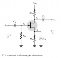
Hello there I've been reading a lot about the J-FET transistors and I was trying to create a self biased JFET amplifier where there is drain resistor and source resistor in the design, I've read a lot and watched the lot YouTube videos but all seem to be explaining about an already made circuit where Rd and Rs are already chosen!
What I want is to start from scratch. and here are some questions:
1) what are the things that I should know about my design other than Idss and Vgs(off) so basically what are the other constants?
2) what are the thing that I am able to vary using my design for example can I choose my load resistance value even if I pe-set the max drain current of my design e.g. "Id or drain current"?
3) when I try following the graphical mode to find the Q-points I track the transition curve and when I choose the middle point of "Idss which is the max jet current" as Q-point (Id=0.5Idss) in the curve so that maximum swings in "drain current Id" could occur I end up setting Rs because[ Idq=(-1/Rs)*Vgsq where q means the q-point values ] and it's voltage so I cannot add "Rd" resistance any more because doing so will change the total series resistant and "Id" would also change as a result.
what am I doing wrong here? should I consider Vds to have 0.5 Vdd? or Id to be 0.5Idss for a J-FET amplifier for max voltage or current swings?
Note that I want to be able to control the LOAD so I want to be able to set my own load resistance also if possible the "Id" too
Attachments
-
 44.9 KB Views: 20


