Seeed XIAO SAMD21 with PIR 250301

Thread Starter

allenpitts

Joined Feb 26, 2011
182
Hello AAC forum,

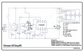
Have built and installed a half dozen closet lights
that use PIRs (motion detectors) to turn three or four
12 volt lamps on for a minute, schematic attached.
Closet_SEED_XIAO_schematic_240920.jpg
The timer is a microcontroller called XIAO SAMD21,
used to be called Seeeduino.

A couple of the closet lights have failed, not because
they won't come on but because they won't go off.

First the PIR was tested to make sure that is
going from high to low which would make the motion detector
the culprit.
But the PIR, which are very reliable, operates
normally in a test circuit.
lnr_3.jpg
The XIAO SAMD21 was then tested and the MC seems
to be normal. Also LED D1 acts as a sort of heartbeat
for the XIAO and LED D1 operates as expected,
blinking on and off every three seconds.
lnr_3_lens.jpg
The only other component that might fail is the
MOSFET. Very difficult to test a transistor once
soldered into the PCB. So, the MOSFET was removed
and replaced with a brand new, freshly tested
unit.

Out of desparation a new XIAO was unpackaged
programmed and installed. Same result. The
load lights come on but will ot go off.

It is unlikely that there is a problem with
the sketch since the same program is being
used in four other systems that are operating
normally.

I am at the end of ny troubleshooting
skills rope.

Thanks

Allen PItts
 

Jerry-Hat-Trick

Joined Aug 31, 2022
781
In the transistor datasheet the Vgs(th) is shown as minimum 2V, typical 3V, maximum 4V. With a 3.3V output from the the XIAO I'm thinking that the design is at best marginal and performance may vary beteen transistor batches. You say the LEDs turn on but not off? Have you tried maybe a 3K3 resistor from gate to ground?

Instead of using 12V LEDs which will have inbuilt resistors in them, had you considered using raw white LEDs with external resistors? Three white LEDs in series with a single current limiting LED might be fine, and changing resistor value would allow you to change the brightness.

Also, the XIAO does seem a bit overkill for the task. An ATtiny85 processor would be ideal and if you are familiar with the Arduino IDE it might be worth exploring - and it's happy with 5V so a bit more voltage into the gate.

If the timing is not critical, a 555 monostable instead of a processor would work well.

Hope this helps, if only to have someone correct me!
 

Thread Starter

allenpitts

Joined Feb 26, 2011
182
Hello AAC forum and Jerry-Hat-Trick,

The excellent reply from Jerry-Hat-Trick is appreciated.

....maybe a 3K3 resistor from gate to ground?...
Perhaps this a typo. Maybe the intent was a 3k
resistor?

Assuming that a 3k resistor was the suggestion,
a 3.3k resistor was connected at Q2 between
the gate and the source (ground). No change
is observed.
3k resistor_at_PCB_241028.jpg
...Instead of using 12V LEDs which will have inbuilt resistors in them,
had you considered using raw white LEDs with external resistors?...


By coincidence this is the setup used in testing when
the PCB is pulled out of the light fixture for testing
as shown in image maeked "System with 5mm LEDs"
This system exhibits the No Turn Off failure when
tested with and without the 3.3 resistor.
5mm_LEDs_w external resistors_250303.jpg
Another set of coincidences is the two alternatives
to XIAO SMAD21 suggested, ATtiny85 and the 555 timer,
describe the path in the evolution of the system.

The Closet System was conceived in 2021 using the 555 timer.
P5L_211018_w_R5_schematic.jpg
The precision for the time that Q2 stays on
is not critical. Plus or minus a minute is sufficient.
But the same No Turn Off failure was encountered
with this circuit. It was pretty well proven
that the source of failure was the capacitor in the RC
network that sets the timing. Because it was not
understood why the capacitor was failing (probably
because inexpensive capacitors were being used)
the 555 timer was abandoned for a microcontroller,
the ATtiny85 in 2023.
Closet_ATtiny85_schematic_230815_white.jpg

Again the No Turn Off failure emerged. Testing
and research pointed to the large aluminum electrolytic
capacitor, C1, 100 uF, was failing, not protecting
the MC against power spikes and causing the ATtiny85
to not turn off the load LEDs.

The change to the SAMD21 was really because
systems being built using the Adafruit Neopixel
ADAfruit Neopixel
led to the conclusion that the ATtiny85 did
not have the processing power or speed
to drive the Neopixel. At this point it
surmised that the SAMD21 was more robust
than the ATtiny85 and was decided to move
all systems, including the Closet system to
SAMD21.

It is agreed that the SAMD21 is overkill
because the Attiny has enough inputs and outputs
to operate the Closet system and the ATtiny85
costs $1.50 and the SAMD21 is $6.50. But
the four bucks is justified if the increased cost
means the difference between failure and
operation as designed.

Perhaps the solution is to go back to tnhe ATTiny
and use capacitors by Panasonic, Rubycon, Nichicon,
reliable, well tested capacitors,
and make sure that the voltage rating is at least
twice the operating voltage of the system.

There is some resistance to going back to the ATiny
in that some time and effort has been spent
developing the SAMD21.

Thanks.

Allen Pitts
 

Attachments

Jerry-Hat-Trick

Joined Aug 31, 2022
781
Flattery will get you everywhere lol

I’d certainly recommend going back to the ATtiny85 for this application if only because it gives you the higher voltage into the transistor gate. The fact that the processor turns on the LEDs but doesn’t turn them off is weird. Is the processor output going low when you put a multimeter on it? And if you are observing the LEDs still on, how are you avoiding re-triggering the PIR? (Analogous to wondering if the fridge light really does go out when you close the door!)

Looking again at the circuit, I think C5 should be in parallel with C2. As shown, it’s just in parallel with C1. The processor needs a clean 5V supply without spikes - the LEDs aren’t too bothered.
 

Thread Starter

allenpitts

Joined Feb 26, 2011
182
Hello AAC forum and Jerry-Hat-Trick,

OK ok, I'll go back to the ATtiny85. Although it seems the XIAO is superior to the ATtiny85, there are three aspects of ATtiny85 where the specs exceed the specs of the XIAO:
1.The output voltage.
2.The price.
3. The real estate on the PCB. (The PCBs are bought by the square mm.)

...is the processor output going low when you put a multimeter on it?...
Yes, there is a test that has been performed several times. First the LED D1 is checked at pin four w the DMM to make sure a good reading is acquired. The DMM goes from 0 volts to 3.3 volts every three seconds as programmed in the sketch.
Then the test probe is moved to pin 3, the output to Q2 gate. The DMM reads zero, then 3.3 when the PIR is triggered and stays 3.3 V for several minutes. The sketch programs the XIAO to be high for twenty seconds and the PIR adds another twenty seconds and so the duration of the load LEDs on should be about forty seconds. This normal duration is observed in the working units.

...And if you are observing the LEDs still on, how are you avoiding re-triggering the PIR?...

The PIR is isolated in a small cardboard box with the lid closed.

Thanks.

Peace.

Allen Pitts
 
Top