secrets for solenoid construction?

Thread Starter

Hamlet

Joined Jun 10, 2015
560
Thanks for all the replies. It seems everyone has a different definition of efficiency, haha.
A long-throw solenoid is inherently inefficient (poor use of power, heat, weak, non-linear).
However, it tends to be quiet, and that's important when you want to stress movement over
noise. And simplicity usually means longevity.
 

Alec_t

Joined Sep 17, 2013
15,156
Using a solenoid to wave a flag or move an arm would result in very jerky unrealistic movement. Have you considered an AC synchronous motor or BLDC motor based mechanism instead? Either could run very quietly.
 

atferrari

Joined Jan 6, 2004
5,029
That's the first thing I thought of when Hamlet mentioned slower, smoother motion with the long throw. Google "cheap linear actuators" and you'll get links to Amazon and Ebay with units with under $20 prices. I'm assuming you don't want to spend $100's on kinetic art.
It is him who is into kinetic art, not me.
 

Bernard

Joined Aug 7, 2008
5,784
For an interesting read put " Why won't my linear stepper motor work?" in " SEARCH FORUMS" box. 513 entries on automated pool cue stick re post # 17.
 
Last edited:

cmartinez

Joined Jan 17, 2007
8,862
To improve the magnetic characteristics of the solenoid, always have a complete magnetic path for the magnetic field through the solenoid.
I was thinking of opening another thread for the following question, so as not to give the impression that I'm trying to hijack this one. But then I thought that the question is not only on-topic, but it will also add valuable info to the TS, once it's answered.

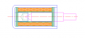
I have a small solenoid designed for 5V operation, it measures about 11 x 11 x 21 mm, with a 4 mm diameter plunger. I disassembled it to take a closer look, and noticed that the plunger has a tapered tip on the back side, and the armature has a rivet at the bottom with a conical hollow matching the plunger's tip. See the following image.

upload_2019-4-29_11-14-48.png​
A plastic barrel around which the coil is wound is shown in green, the steel armature is shown in blue, the plunger is magenta, and the coil (#32 ga) is shown in orange.

The solenoid's force is definitely at its maximum when its plunger is 1.5mm away from completely reaching the rivet (as exactly depicted in the previous image). I'm sure that the arrangement has to do with concentrating the field lines passing through the rivet and the plunger, magnetizing both, and thus maximizing attractive force.

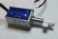
The solenoid's housing is made of steel, and it's "U" shaped (the rivet is installed at the bottom of that housing). See picture.

upload_2019-4-29_11-17-2.png​

My question is, is said housing also necessary to concentrate the field lines? Or would the solenoid function just as well with a plastic housing, provided that the steel rivet is installed in the same place?
 

MaxHeadRoom

Joined Jul 18, 2013
30,817
I have a small solenoid designed for 5V operation, it measures about 11 x 11 x 21 mm, with a 4 mm diameter plunger. I disassembled it to take a closer look, and noticed that the plunger has a tapered tip on the back side, and the armature has a rivet at the bottom with a conical hollow matching the plunger's tip. See the following image.
The plunger is usually considered the Armature.
i.e. The part that is in motion.
The coil section is the stator.;)
Max.
 

atferrari

Joined Jan 6, 2004
5,029
I was thinking of opening another thread for the following question, so as not to give the impression that I'm trying to hijack this one. But then I thought that the question is not only on-topic, but it will also add valuable info to the TS, once it's answered.

I have a small solenoid designed for 5V operation, it measures about 11 x 11 x 21 mm, with a 4 mm diameter plunger. I disassembled it to take a closer look, and noticed that the plunger has a tapered tip on the back side, and the armature has a rivet at the bottom with a conical hollow matching the plunger's tip. See the following image.

A plastic barrel around which the coil is wound is shown in green, the steel armature is shown in blue, the plunger is magenta, and the coil (#32 ga) is shown in orange.

The solenoid's force is definitely at its maximum when its plunger is 1.5mm away from completely reaching the rivet (as exactly depicted in the previous image). I'm sure that the arrangement has to do with concentrating the field lines passing through the rivet and the plunger, magnetizing both, and thus maximizing attractive force.

The solenoid's housing is made of steel, and it's "U" shaped (the rivet is installed at the bottom of that housing). See picture.


My question is, is said housing also necessary to concentrate the field lines? Or would the solenoid function just as well with a plastic housing, provided that the steel rivet is installed in the same place?
@cmartinez
Hola César. Sorry, I fail in identifying the rivet. Not even sure how it looks.
 

cmartinez

Joined Jan 17, 2007
8,862
The plunger is usually considered the Armature.
i.e. The part that is in motion.
The coil section is the stator.;)
Max.
Thanks for the correction, Max ... technical English always gets to me... :oops:

@cmartinez
Hola César. Sorry, I fail in identifying the rivet. Not even sure how it looks.
The rivet can't be seen in the picture, but it's shown in the drawing.

upload_2019-4-29_11-53-39.png​
 

Thread Starter

Hamlet

Joined Jun 10, 2015
560
My question is, is said housing also necessary to concentrate the field lines? Or would the solenoid function just as well with a plastic housing, provided that the steel rivet is installed in the same place?
Thanks for hijacking my thread.

The inter-mesh between rivet/plunger leads me to think it was designed for strong holding force.
When the armature/plunger is seated, the frame/stator + armature
completes a magnetic circuit that is roughly doughnut shaped, where the armature is
occupying the space where the doughnut hole would be. The magnetic circuit is a torus shaped field
that is stronger when a magnetically permeable materiel is overlaid the region it occupies (metal frame/stator, + metal armature).
I think it would have stronger pull-in if the front part of the bracket were separated from the sides/rear&rivet,
and attached to the armature, so it was mobile. This wouldn't change the holding force, however.

So, in answer, it wouldn't be as strong with just a rivet and plastic body.
 

cmartinez

Joined Jan 17, 2007
8,862
Thanks for hijacking my thread.

The inter-mesh between rivet/plunger leads me to think it was designed for strong holding force.
When the armature/plunger is seated, the frame/stator + armature
completes a magnetic circuit that is roughly doughnut shaped, where the armature is
occupying the space where the doughnut hole would be. The magnetic circuit is a torus shaped field
that is stronger when a magnetically permeable materiel is overlaid the region it occupies (metal frame/stator, + metal armature).
I think it would have stronger pull-in if the front part of the bracket were separated from the sides/rear&rivet,
and attached to the armature, so it was mobile. This wouldn't change the holding force, however.

So, in answer, it wouldn't be as strong with just a rivet and plastic body.
Sounds reasonable, but then again, why is the coil wound around a plastic tube instead of a metal one? Why is it more important to have a metal outside frame than a metal inner tube?
 

kubeek

Joined Sep 20, 2005
5,796
It is the same reason why transformers use core on the outside of the coil as well as on the inside. You use the outside metal to "conduct" the magnetic field as efficiently as possible back to the other side of the solenoid, without scattering all around the outside of the core.
(added a clarification to the last sentence)
 
Last edited:

djsfantasi

Joined Apr 11, 2010
9,237
How long a throw are you talking about? How big is the flag?

I don’t know the answers to this question, so I can’t tell if a solenoid is the best solution.

Note: I’ve done a few “art” animation projects. That’s where my questions come from.

I would have first considered one of these options, several of which have been mentioned.
  • Rotary to linear motion converter
  • Worm drive
  • Stepper Motor
  • Geared motor direct drive
  • Hobby Servo motor
Several of these do not require any complicated electronics. Others use standard techniques. So what are you exactly trying to do? And several are simpler than a solenoid.

And I’m sure that there are others. So what exactly are you trying to do?
 

cmartinez

Joined Jan 17, 2007
8,862
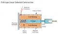
Here is a demo of the magnetic field completed by the outer metal frame.
Max.

View attachment 176288
Thanks, I think I have a clearer picture now of how a solenoid works. BTW, I'm building a solenoid right now that is going to have to work submerged in water (plain drinking water) ... it's going to be a challenge to coat its frame to perfection to protect it from rust ... wish me luck
 

kubeek

Joined Sep 20, 2005
5,796
Thanks, I think I have a clearer picture now of how a solenoid works. BTW, I'm building a solenoid right now that is going to have to work submerged in water (plain drinking water) ... it's going to be a challenge to coat its frame to perfection to protect it from rust ... wish me luck
If you don´t need super efficiency, then think about epoxy coating the whole structure, just keep the barrel diameter clear. Something like the green current transformer here (with different insides of course) https://standexelectronics.com/wp-content/uploads/2014/10/current-sense-transformer-toroidal.png
Or a variation on impeller type aquarium pump.
 
Top