Scoreboard Project Cont;

Thread Starter

Oxbo Rene

Joined Feb 20, 2009
201
This relay is a T73S5D24-12B.
Even though it says "Potter& Bloomfield" on it, doing a search of the number the PDF comes up as "Tyco".
I figure they're the same............
The "Must Operate Voltage" rating for 12V is 7.8 volts, so, I figure that'll be OK (having already incorporated the pin #3 diode in the PCB layout.
Can you concure ?
The only time the relays will be on will be when the clock is at "0000" or the preset value.
I don't think they'll be hurt by being on the small amout of time the clock will be at 0000, etc.
I have one on my mailbox circuit that's lasted for years, staying energized, only to de-energize when the mailbox door is opened (breaking the circuit).
OK, Sarge, I appreciate your assistance...........
Oxbo
 

Thread Starter

Oxbo Rene

Joined Feb 20, 2009
201
BIG PROBLEM ! ! ! ! !
Got my "Buzzer timer" circuit built and installed = everything works fine !
Got my "Period Count" board built and installed = Works terrible !
Is a long story, this period count board is a replica of the one in the "Console".
Pwr'd up and LEDs #1,2,3 light up, but #4 is off, start cyling through by pushing the advance button on the console and when I light up #2 LED on the console, #4 led on big board lights up (all three others stay lit) advance again, #4 goes out (#1,2,3 stay lit).
Then I realize, the two circuits only have the "advance" (output from a 555) pulse in common.
Recalling back when we designed the console period count circuit, Bernard pointed out that I should use the one up from zero output so as the thing will have an "all LEDs out" condition at startup, and that seemed to work, however, later on it got to where at pwr on #1 LED would always come on, and sometimes a couple would come on at pwr up, I didn't see it as a big problem, the operator would just have to cycle through back to "All out".

NOW, we get to the big board, I had decided to just fabricate another period count board and use the advance pulse to advance both boards, thus, just sent the pulse through the 25-pin cable to the big board, etc.

Now working with it (BB period count) it ain't working properly.
Replaced the 4017, = no change
Replaced the CD4081BE (AND gates) and now different lights light up but far from proper.
Replaced CD4081BE with CD4073B (another AND gate chip) and it works almost but still not proper, but real close.
I realize at this point, if they (console and BB period count boards) both started up at "all-out" at pwr up things would be cherry, however, they don't, and now I'm faced with a synchronous problem.
BUT, check this out ! !
I decided to play with the buzzer by just hitting the PB (push button) and making it sound, AND, when I did that , the dad-gummed LEDs switched around! The more I sounded the buzzer, the more the LEDs would randomly switch on and off!
The only thing the two circuits have in common is that they both tie back in to the output of the DC pwr supply which is supplied via (+) & (-) terminal strips.
So, loose connection? I made sure everything went together nice and tightly. I would tap around on the Period count board with a plastic device = no change, move wires around = no change, sound the buzzer = LEDs would randomly switch around, sometimes not. Cheeeeeze ! ! !
At this point I think I might have to come off the ULN2004A chip back in the console to also drive the big board LEDs (I had four extra wires available in the 25-pin cable) and I think the ULN2004A can handle the extra current BB LEDs = 70ma ea.
Your comments certainly appreciated......
Oxbo

Oh, another thought, the little wires in the 25-pin cable are pretty small, I think they are only rated at 50ma, so might have to add some more buffering, etc.....
 

Attachments

Last edited:
As for the LED's, try pulling your +12v connection from pin 9 of the ULN2004A. That can float (unless you're trying to increase current through the whole chip - but then you will need other components).

Grounding pin 9 will light all the LED's at once. (Works great as a test lamp function).
 

Thread Starter

Oxbo Rene

Joined Feb 20, 2009
201
Appreciate your suggestion "Whatsthatsmell".
Haven't had time to get back to the board yet.
Just now devoting some time to coming up with my fix.
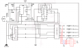
Attached is what I see as a pretty safe fix (in red).
Would certainly appreciate any comment if it looks as if it "won't" work.
 

Attachments

Thread Starter

Oxbo Rene

Joined Feb 20, 2009
201
Well;
Got my fix (see above schematic) in and still it ain't right.
Have troubleshot it and find I have a perfect signal coming off the inverters, they work perfectly (12.02V on // .002V off).
So, for some reason the ULN2004A doesn't like the LEDs.
These LEDs I purchased at a truckstop in Kentucky. They are designed for the big 18 wheeler trucks, etc. They are made up of several LEDs encased in a red reflector case, the directions said they include the proper resistors, etc, and all ya got to do is plug em in, which I have done, testing them, etc.
They are supposed to draw 70ma pr unit, etc.......
So, I see them as one led that requires 12V @ 70ma, and they work just fine as that.
Have replaced the ULN2004A twice and see no change.
What I get is, when I light up the first LED on the console, all the LEDs on the big board light up but, the first one is bright, the rest are dim. Advancing to LED #2 on the console, all the LEDs on the big board light up but now the second one is brighter than the rest (actually the dim ones mean that not all the LEDs in the package are lighting up..
Same for #3, however selecting #4, all the LEDs on the big board go out.
SO, heck with it, I don't know why they act the way they do, but,have decided to go with individual transistor switches using PN2222's rather than the ULN2004A.
AND, if that don't work, I'll by-golley use relays on em ! ! !
Thanks for lettin me share :)
Oxbo
 

Thread Starter

Oxbo Rene

Joined Feb 20, 2009
201
"Right.
With a 4017 Johnson counter, one output is always high, the rest are always low.
When power is first applied, the counter may be in a random state; any one of the outputs may be high.

If you want to make certain that they are all off when you power it up, connect an 0.1uF capacitor from the RESET input (pin 15) to Vdd (+V)."


Tx's for that ......
 

Thread Starter

Oxbo Rene

Joined Feb 20, 2009
201
OK,
Here's the circuit (1-of-4) I plan on using to drive the LEDs.
I think this will work, will have to breadboard it in the morning.
Apparently I was mistaken on the amount of current the LED pkg's draw.
I hooked one up to straight 12V and it showed 30ma current, so I figure that the transistor Vce will be .2v (best I can recon from the data sheet).
That'll leave 11.8v to run the LED, and thus a slightly smaller current draw.
 

Attachments

Thread Starter

Oxbo Rene

Joined Feb 20, 2009
201
Well;
Just to put the period on the end of a sentence.
Here's the last couple pics of the modified circuit for the period count, etc.
I sense that perhaps I might have worn out my welcome here on the forum.
I definitely agree, this thing has drawn on toooo long.
It's like having a bad woman, ya just can't wait till she's gone....
Unfortunately, I can't let it go, but, I can relieve you guys from it's/my aggravating persistence.
I could've never gotten this far without this forum and especially Sgt Wookie.
So, thanks so much for everything.
Last post ...........
Oxbo
 

Attachments

Thread Starter

Oxbo Rene

Joined Feb 20, 2009
201
Hi folks, Oxbo here. been long, long, long time since I was here working on that scoreboard = I finally did get it working and gave it to my son for his wrestling team at school (he was coach). He had it six months , then gave it to the maintenance man at his school = I didn't speak to the fellow for many years for him doing that , and still think about all the time and money I put into that thing, plus the time all these folks on this forum put into helping me ...... I guess you can understand why I'll never be doing anything like that for anybody else (cept myself) again ...... Have a nice day
Oxbo
 
Top