Schmitt Trigger output issues

Thread Starter

Xanasg

Joined May 13, 2015
6
Hey guys (and girls)

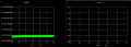
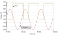
I'm using a dual supply condenser microphone amplifier and schmitt trigger with positive feedback, to convert an amplified sinus signal (from mic) to a digital signal. A LTspice simulation of the circuit works perfectly fine, but the physical model doesn't care if there is a voltage supply or not, can anyone see why?

The circuit connections is drawn in Blackboard and is attached as the file "schmitt_trigger.PNG"
(The resistor values and comparator isn't the same in Blackboard as in the physical model, we are using the comparator LM311N, and the resistors shown in LTspice)

Thanks in advance for any help!
 

Attachments

JoeJester

Joined Apr 26, 2005
4,390
Have you read the datasheet on the LM311N?

Did you notice it was and open collector comparator?

on edit .... Your output should look like:
 

Attachments

Last edited:

Thread Starter

Xanasg

Joined May 13, 2015
6
Thanks for the reply @JoeJester

Looking at the datasheets for LM111-N, LM211-N and LM311-N there is no word mentioning open collecting ?

Also the square wave in the simulation is from the feedback to non-inverting input. :)

Regards Ivan
 

MikeML

Joined Oct 2, 2009
5,444
To make your LTSpice simulation behave like the LM311 you are using, go and find the LM311 Spice model, and import it into LTSpice's library. Alternatively, use the built-in model for the LT1011. The specs for the LT1011 are better than a LM311, but you should be able to get the Schmitt Trigger working...

Both the LM311 and LT1011 have "open-collector" outputs, so you will have to add an external pull-up resistor.
 

MikeML

Joined Oct 2, 2009
5,444
Questions and suggestions:

Why do you think you need so much hysteresis?

What is the allowed input range of pin3 (in-)?

Using the LM311, should pin 4 (Vs-) be tied to oV or -5V? Why?

Where should pin 1 (gnd) be tied?

What to do with pins 5 & 6 if you are not using them?
 

Thread Starter

Xanasg

Joined May 13, 2015
6
Hey again @MikeML

I've found following answers to your questions/solutions:

Why do you think you need so much hysteresis??
- We don't, I've tuned it down again so that the hysteresis has threshold between 400mV and 600mV

What is the allowed input range of pin3 (in-)?
- According to datasheets (and how I read them) it's +-15V

Using the LM311, should pin 4 (Vs-) be tied to oV or -5V? Why?
- We tie it to 0V because we want the output to reach from 0V to 5V (binary 0 and 1)

Where should pin 1 (gnd) be tied?
- I can't figure out whether this can just go to ground or if it needs some sort of feedback from the circuit. Other examples of circuits with LM311 shows a direct connection from pin4 and pin1 to ground.

What to do with pins 5 & 6 if you are not using them?
- About pin5&6 I've read that they can regulate offsets, and if you don't want to use them, they could be left open or tied together.

This is the best I could do for now. The schmitt trigger still doesn't work as expected, but the pull-up resistor worked liked a charm in LTspice together with the LT1011, cheers
 

MikeML

Joined Oct 2, 2009
5,444
Hey again @MikeML

I've found following answers to your questions/solutions:

Why do you think you need so much hysteresis??
- We don't, I've tuned it down again so that the hysteresis has threshold between 400mV and 600mV
Good. I was going to suggest that.

What is the allowed input range of pin3 (in-)?
- According to datasheets (and how I read them) it's +-15V
A more careful reading of the data sheet shows that both inputs have to remain between Vs- and Vs+. Since the input from the preamp swings below 0V, the Vs- pin of the LT1011/LM311 must be tied to -5V to satisfy the allowed operation for the input pins.

Using the LM311, should pin 4 (Vs-) be tied to oV or -5V? Why?
- We tie it to 0V because we want the output to reach from 0V to 5V (binary 0 and 1)

Where should pin 1 (gnd) be tied?
- I can't figure out whether this can just go to ground or if it needs some sort of feedback from the circuit. Other examples of circuits with LM311 shows a direct connection from pin4 and pin1 to ground.
You have the role of pin 1 and pin4 swapped. Pin 4 defines the allowed range of the inputs. Pin 1 defines the output voltage swing, so you should tie pin 1 to 0V = gnd = the tap between the two 5V supplies.

What to do with pins 5 & 6 if you are not using them?
- About pin5&6 I've read that they can regulate offsets, and if you don't want to use them, they could be left open or tied together.
The TI data sheets shows them tied together if not used.

This is the best I could do for now. The schmitt trigger still doesn't work as expected, but the pull-up resistor worked liked a charm in LTspice together with the LT1011, cheers
Here is my suggestion: Note that I raised the values of the resistors, keeping the ratios. I greatly reduced the hysteresis. You can actually see the hysteresis at V(cl)

t1011.gif
 

JoeJester

Joined Apr 26, 2005
4,390
Mike,

It's all the rage these days. Provide schematics or breadboards with components not related to what you are doing and then asking for assistance on why it's not working.

It's your fault your not understanding what he is doing. Clear communication is so last century.
 

Thread Starter

Xanasg

Joined May 13, 2015
6
Hehe, sorry guys..!

As I mentioned in the start of the thread, the blackboard schematic doesn't have the right components like @JoeJester mentions...

But I can announce that the trigger now works ! But we get an unexpected error in the output... It's hard to explain, check for yourselves :)

The error lies in a small signal swing at -800mV where the output goes Low for a moment...
 

Attachments

Top