Hello,
I am designing a low cost solution for measuring voltage on the mains 220V with a precision target of 0.1V.
My requirements are 4kVrms galvanic isolation between mains and the low voltage circuitry.
I am measuring the output signal using an esp32
The transformer should be small and cheep.
It must be able to handle transients/ voltage spikes
Measurment range should be within 190 and 250V AC 50Hz
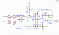
This is the schematic i would like to get opinions about:

The general working principal is this:
The input resistors limit the current down to a few mA, then i create a voltage devider 21:1 from 230V to 11V (safe)
The 11V then goes to the voltage comarator circuit which optputs the difference between 9V on the - pin and the 11V on the + pin. The output is 2 V
Any negative voltage on the + pin goes to GND and doesnt make it to the MCU pin.
The 3.3V power to the opamp also limits the optput signal to 3V, which is the maximum the MCU pin can handle.
I have already used the op amp stage sucessfully for measuring 0-15V input signal but that was with a big expensive transformer, now i would like to use something smaller like this part from Pulse electronics.
Is this a sound design? I am mostly concerned the transformer is too small and doesnt have good enough slew rate for this.
Or the resistors (which are SMD 1206 1%) are not wired correctly.
Any design tips?
I have also looked at isolated opamps solutions before, but the seperate power supply for them and the cost parts drive the cost of the circuit to 6€+, which i think is too much.
Thank you for your feedback
I am designing a low cost solution for measuring voltage on the mains 220V with a precision target of 0.1V.
My requirements are 4kVrms galvanic isolation between mains and the low voltage circuitry.
I am measuring the output signal using an esp32
The transformer should be small and cheep.
It must be able to handle transients/ voltage spikes
Measurment range should be within 190 and 250V AC 50Hz
This is the schematic i would like to get opinions about:
The general working principal is this:
The input resistors limit the current down to a few mA, then i create a voltage devider 21:1 from 230V to 11V (safe)
The 11V then goes to the voltage comarator circuit which optputs the difference between 9V on the - pin and the 11V on the + pin. The output is 2 V
Any negative voltage on the + pin goes to GND and doesnt make it to the MCU pin.
The 3.3V power to the opamp also limits the optput signal to 3V, which is the maximum the MCU pin can handle.
I have already used the op amp stage sucessfully for measuring 0-15V input signal but that was with a big expensive transformer, now i would like to use something smaller like this part from Pulse electronics.
Is this a sound design? I am mostly concerned the transformer is too small and doesnt have good enough slew rate for this.
Or the resistors (which are SMD 1206 1%) are not wired correctly.
Any design tips?
I have also looked at isolated opamps solutions before, but the seperate power supply for them and the cost parts drive the cost of the circuit to 6€+, which i think is too much.
Thank you for your feedback