Schauer C7612 Battery Charger

Thread Starter

gejettest

Joined May 14, 2023
2
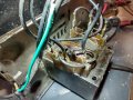
Hello, I have an older Schauer C7612 6/12 volt 10amp battery charger that quit on me.
Sure, I could pitch it but I love a challenge to repair it.
Factory no help, no parts, they admit they didn't even make it in house.
Anyway, I was trying to charge a very dead battery. Unit would burst energy then click off, repeated all night long, finally no output.
I took the unit apart, checked for voltages, etc.
I am an aircraft A&P by career, but not an electronics master by any means.
I did find my circuit breaker fried but that is on the DC output side. Not the AC input side.
Transformer has many tabs, like 9, so I'm not sure what to test.
I also found a melted piece of solder next to a diode.
 

Attachments

MisterBill2

Joined Jan 23, 2018
27,501
It looks like the transformer has been overheated, and it also looks like it has an embedded thermal fuse. Beyond that, it also looks not large enough to deliver ten amps. So it may be worth the effort to replace the transformer and the rectiifier, if it is an older selenium type.
 

MisterBill2

Joined Jan 23, 2018
27,501
It looks like the transformer has been overheated, and it also looks like it has an embedded thermal fuse. Beyond that, it also looks not large enough to deliver ten amps. So it may be worth the effort to replace the transformer and the rectifier, if it is an older selenium type. I do see some other things attached to the transformer, which may not be transformer related. If there is a solder blob near a rectifier then probably that has failed.
I recommend repairing it if parts can be had at less than list price from an expensive supplier. A new charger will have a switching supply that is far less forgiving of any abuse. And switchers are not so easily repaired for most.
An exact replacement transformer is not mandatory, but any substitute will need to be fairly close.
And of course the breaker is on the DC side. Does the transformer put out any voltage at all?? If the thermal fuse has failed, I would replace it eventually, and bypass it for testing to be sure the transformer is not damaged.
 

Dodgydave

Joined Jun 22, 2012
11,395
Easily to test, get a multimeter and check the primary windings, remove the spade terminals on the secondary side and check those, it will be a 12V centre tap type, check the bridge rectifier for shorts.
 

MisterBill2

Joined Jan 23, 2018
27,501
Easily to test, get a multimeter and check the primary windings, remove the spade terminals on the secondary side and check those, it will be a 12V centre tap type, check the bridge rectifier for shorts.
When checking be sure to keep track of which wires go where, from the pictures I see that the correct connections are not obvious, and that there are more connections than usually found in a battery charger.
 

Thread Starter

gejettest

Joined May 14, 2023
2
When checking be sure to keep track of which wires go where, from the pictures I see that the correct connections are not obvious, and that there are more connections than usually found in a battery charger.
Sure, I can use a multimeter, but with 9 wires on the transformer how do I know what is what? Lol
Here is what I would like to do, I could open the program in "Paint" and label each wire.
Would that help you guys to point me in the right direction for testing?
Thanks!
 

Dodgydave

Joined Jun 22, 2012
11,395
The transformer will have 3 wires on the secondary side, and probably 4 on the primary for different mains voltages. Mark the wires with tape or white marker pen and also where it goes.
 

MisterBill2

Joined Jan 23, 2018
27,501
As I look at the pictures, there are indeed more wires coming from the transformer that what is common and easily understood. So it is NOT SO SIMPLE!!!
Part of the testing can be done without disconnecting any wires. So the first check is to measure between the blades of the line plug. That resistance should be less than 1000 ohms, probably less than 100 ohms. If it checks open circuit then that is a start.. Next is inside the charger. The test is seeing where the break in the circuit is. For this you will need to connect one meter lead to the pins on the line plug, one at a time, and with the other, probe line cord wires inside the charger. At some point there will be some device that shows a connection on one terminal but not on the other terminal.That device is a suspect.
 

rogerbent

Joined Nov 26, 2022
2
As I look at the pictures, there are indeed more wires coming from the transformer that what is common and easily understood. So it is NOT SO SIMPLE!!!
Part of the testing can be done without disconnecting any wires. So the first check is to measure between the blades of the line plug. That resistance should be less than 1000 ohms, probably less than 100 ohms. If it checks open circuit then that is a start.. Next is inside the charger. The test is seeing where the break in the circuit is. For this you will need to connect one meter lead to the pins on the line plug, one at a time, and with the other, probe line cord wires inside the charger. At some point there will be some device that shows a connection on one terminal but not on the other terminal.That device is a suspect.
Hey gejettest,
I just worked on this exact charger and all that was wrong turned out to be an open thermal fuse. Since this is not a replaceable item (most likely since it is potted), my customer requested to merely bypass it. When I did that, the charger worked just fine.

This is a very simple change, though there is no protection for the primary if this is done! In your last image, where one of the mains wires terminates to the transformer where the short jumper goes to the little two-terminal device (the thermal fuse), move the mains connector to the adjacent terminal with the jumper that goes to the other lead on the thermal fuse. This bypasses the thermal fuse without having to desolder anything.
 

Attachments

MisterBill2

Joined Jan 23, 2018
27,501
There should be a fuse to protect things if there is a serious overload or failure. So use the chargers current rating to figure the watts out, then use that calculated power to figure the input current for peak output. Then use a time-lag fuse of an amp more than that current as the protection device.That will protect against fires while avoiding nuisance fuse failures.
 

rogerbent

Joined Nov 26, 2022
2
There should be a fuse to protect things if there is a serious overload or failure. So use the chargers current rating to figure the watts out, then use that calculated power to figure the input current for peak output. Then use a time-lag fuse of an amp more than that current as the protection device.That will protect against fires while avoiding nuisance fuse failures.
I totally agree. I've done the calculations and I figure a 3A, slo-blo fuse should work just fine. It may be a bit of overkill, but certainly should offer more protection than straight wiring!
 

MisterBill2

Joined Jan 23, 2018
27,501
Three amps is a very reasonable sized fuse for a medium smaller battery charger.
I regard the of using a thermal fuse inside the transformer or motor as being nastypoor designing.
 
Top