SBC with jumpers and a double sided board

Thread Starter

mik3ca

Joined Feb 11, 2007
189
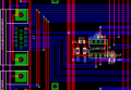
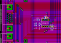
I'm still working on my SBC, and I was trying to figure out a good way to make the whole circuit on a single-sided board, but now I might have to use double sided board.

However, I still have the following restrictions.

1. all holes need to be filled in. This means the holes that make the via's must not be left open. I do have jumper blocks which function like 5 dip switches all turned in the ON position that I can use as 5 wire jumpers in series.

2. I must be able to solder the via as an amateur would do it. In other words, I want to avoid taking my board into a professional shop, and do the whole thing myself.

Given that, all I need is a way to construct my board in software so that the via's are pre-defined, and the board is auto-routed.

I am using Eagle. Because it can accept code, I was wondering if anyone can tell me how I can define specific via points. On a 2-sided board, Eagle normally defines vias at random locations which is no good to me.

If there is software better than Eagle that I can use, let me know. Thanks.
 

scubasteve_911

Joined Dec 27, 2007
1,203
Hi,

Autorouting is not advised for simple boards, just avoid it altogether if you can. Most autorouters work poorly. The only way you can make a decent autoroute is to define very well detailed design rules.

I'm not sure what you mean about the vias.. You just place an ordinary via in software, make the hole a bit bigger (maybe 0.038"+) and solder in a wire.

Getting a PCB made is really cheap and I think it has gotten to the point where most people can afford the service. www.33each.com , if you're a student, you can order a single unit for 33$ plus shipping, otherwise you must order 3 PCBs for 33/each.

Steve
 

beenthere

Joined Apr 20, 2004
15,819
I agree with scubasteve about autorouting - it may work with the really great CAD programs, but it's pretty lame otherwise. You only get good results with manual placement.

With my old CAD, when I run a line and change the layer with the menu, a via is placed at that point. You have total control of the via's shape and both diameters. Keep the via's small and use a #75 drill for the hole, 30 ga wire for the connection.
 

SgtWookie

Joined Jul 17, 2007
22,230
As has already been said, forget the autorouting. It's singular goal is to connect everything, placement and run length be danged.

Don't worry about using your DIP jumpers, as you'll get frustrated if you have to cross an 8- or 16-bit bus. You can just use wire jumpers on the top side of the board.

Once you get "stuck" and need to jump across a few traces, figure out what length jumper you need, and go back to the schematic.
Look in jumper.lib under J for various length jumpers. Snip a section out of your wiring in your schematic, and plug in the closest-length jumper you found.
The supplied lengths are 5, 7, 10, 12, 15, 20 and 30 (all mm, rounded off).
If you don't have jumper.lib, you can find it on Cadsoft's website.
After you make the board, just use bus wire for the jumpers.

For board-making techniques, check out Tom's site:
http://www.fullnet.com/~tomg/gooteepc.htm
 

beenthere

Joined Apr 20, 2004
15,819
It adds vias, but keeping all the horizontal traces on one side and the verticals on the other makes the layout easier, too.

I did a dual-sided manual layout on an SBC with a 68HC11 & ground and power planes. through-hole components are handy because the leads make via connections nicely, and you can get a bunch of traces under a resistor. Wouldn't want to mess with a BGA device, though.
 

thingmaker3

Joined May 16, 2005
5,083
Why do they put a "permanent press" setting on irons? Why do women use moisturizers when moisturizers deprive the skin of its ability to moisturize itself? People do silly or harmful things all the time for no good reason. Auto-routers are just one example.
 

SgtWookie

Joined Jul 17, 2007
22,230
They're not bad if you have the time to set up tons of rules, and are making multilayer boards.

But unless you're going to be doing a LOT of routing on many very similar kinds of projects, it will take you a lot of time just to set up all of the rules, when you could be actually cranking out a couple of boards.

But you're not doing multilayer; you're just doing a two-sided board. Trying to do routing on a single-sided board when you're dealing with memory/data/address busses along with I/O pins would be pretty frustrating, if not impossible. Jumpers have more inductance than traces do. Busses should have equal lengths for each run, unless you like diagnosing timing problems. But unless you set up rules for such things, it's a free-for-all.

My projects are too varied in nature to spend a lot of time setting up a ton of rules.

The "ratsnest" tool is very handy when you're first placing components on the board. It helps a lot to be looking at your schematic simultaneously.

When I'm doing a two-sided board, I basically run everything horizontally on the bottom, and vertically on the top. That's not a hard-and-fast rule; sometimes it's much more convenient to do it the other way around. After routing everything, I may go back and see if I can eliminate vias without causing problems by combining some of the traces on a single layer.

The polygon tool (below the arc tool) is great for doing "copper pours". Once you have everything routed, click the polygon tool's icon, select the layer to do the pour, click one of the the right-angle wire bends, zero miter, zero the width, set isolate to 0.012, spacing to 0.05 - then click on the lower left corner of your board, then the upper right, and the lower left again to close the polygon. Then click the Ratsnest icon - presto, your whole layer is copper-filled. You can still ripup/route, and the polygon fill will seemingly magically "pour" around what you're doing. Best to wait until you're about done though, as it does take some CPU time to do that.

See the attached for an example.
 

Attachments

scubasteve_911

Joined Dec 27, 2007
1,203
Just a quick note about horizontal-top vertical-bottom type routing. This is a very good method to prevent crosstalk between two signal layers. If traces are run next to eachother on both layers, then their capacitance is increase and thus the coupling effect.

mik3ca,

If you know the difference between a good layout and a poor one, and have tried using autorouters, then you will know that they are pretty much hopeless. I have used very expensive autorouters with a good set of design rules. I can do a much better job :) The only real place for them is extremely high-density boards that are multilayer. Even these you will route all critical traces first, then let the autorouter take care of the rest.

Steve
 
Top