 Facebook
 Google
 GitHub
 Linkedin
Good day all!
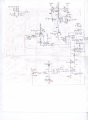
I have recently completed an automatic water pump control circuit for a solar powered water pump.
It will sense water levels (with remote sensor, copper wire) and run the pump according to the water /sensor levels.
Also it has a -run dry- protection feature that will shut off the pump if the -run dry- sensor loses contact with the water.
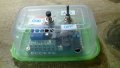
OK, I designed and built the circuit using some -old- SA555 T.I. chips that I had on my bench from maybe 5 or 7 years ago. And the circuit runs as expected.
Now, I ordered from China some 'T.I.' NE555 chips and to my surprise the timer delay function for the -run dry- feature no longer works as it does with my 'old' T.I. chips from many years ago!!!
Basically, the observed problem involves Q1 and D1 circled in RED. Q1 should not be conducting when the start up timers is active and counting.... (when the start up delay timers expires then Q1 begins to conduct.).
With the new Chinese NE555 chips , Q1 conducts ALWAYS except for when I remove the Ground to D1. Then the circuits runs normally as with the 'old' T.I. SA chips. So, the path to ground to bias Q1 is thru D1 with the Chinese chips. I don't understand because if that is the case then why does Q1 NOT bias thru the D1 ground when using the old T.I. SA chips?
So, I put the old 'T.I.' SA555 chip back in the circuit and all functions are a GO.
So, my question is: Can there really be that big of a difference in these common 555 chips to make my circuit STOP functioning?
Sorry about the hand drawn circuit. Didn't have time to LTspice it.
I would appreciate any and all commentaries, probably I am overlooking something very obvious here.....
Thanks in advance, just let me know if anyone requires more info.
lost_bro
I have recently completed an automatic water pump control circuit for a solar powered water pump.
It will sense water levels (with remote sensor, copper wire) and run the pump according to the water /sensor levels.
Also it has a -run dry- protection feature that will shut off the pump if the -run dry- sensor loses contact with the water.
OK, I designed and built the circuit using some -old- SA555 T.I. chips that I had on my bench from maybe 5 or 7 years ago. And the circuit runs as expected.
Now, I ordered from China some 'T.I.' NE555 chips and to my surprise the timer delay function for the -run dry- feature no longer works as it does with my 'old' T.I. chips from many years ago!!!
Basically, the observed problem involves Q1 and D1 circled in RED. Q1 should not be conducting when the start up timers is active and counting.... (when the start up delay timers expires then Q1 begins to conduct.).
With the new Chinese NE555 chips , Q1 conducts ALWAYS except for when I remove the Ground to D1. Then the circuits runs normally as with the 'old' T.I. SA chips. So, the path to ground to bias Q1 is thru D1 with the Chinese chips. I don't understand because if that is the case then why does Q1 NOT bias thru the D1 ground when using the old T.I. SA chips?
So, I put the old 'T.I.' SA555 chip back in the circuit and all functions are a GO.
So, my question is: Can there really be that big of a difference in these common 555 chips to make my circuit STOP functioning?
Sorry about the hand drawn circuit. Didn't have time to LTspice it.
I would appreciate any and all commentaries, probably I am overlooking something very obvious here.....
Thanks in advance, just let me know if anyone requires more info.
lost_bro
Attachments
-
 1,020.6 KB Views: 62
 -
 615.8 KB Views: 41
 -
 601.7 KB Views: 39
Last edited:


