[S.T. 5 ] - Limiting circuit with Zeners

Thread Starter

PsySc0rpi0n

Joined Mar 4, 2014
1,755
Hi...

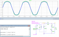
I have the attached circuit to simulate and find the Rs.
I know we need to consider at least 9 situations for this circuit.
  1. Z1 - OFF || Z2 - OFF
  2. Z1 - OFF || Z2 - ON -> IMP
  3. Z1 - ON || Z2 - OFF -> IMP
  4. Z1 - ON || Z2 - ON -> IMP
  5. Z1 - ZEN || Z2 - OFF -> IMP
  6. Z1 - ZEN || Z2 - ON
  7. Z1 - OFF || Z2 - ZEN -> IMP
  8. Z1 - ON || Z2 - ZEN
  9. Z1 - ZEN || Z2 - ZEN -> IMP
Know I'm a bit confused about which situations are impossible. I think it's impossible 2, 3, 4, 5, 7, 9.
Please, confirm whether I'm right or wrong.
 

Attachments

ericgibbs

Joined Jan 29, 2010
18,766
hi psy,
I am not sure what you are asking.?
Can you define what you mean by the parallel symbol '||'.?

I have modified your sim and posted a plot for discussion.
 

Attachments

Thread Starter

PsySc0rpi0n

Joined Mar 4, 2014
1,755
That was supposed to be a simple table telling all the possibilities and the real possibilities... The || symbol was just to separate columns!

We need to work out an average value for Rs so that the circuit works within 10% and 90% of the zener's working range regarding currents!

I mean, we are given the zener's (max or nominal) power dissipation value, the Breakdown voltages and with this we can calculate the circuit's current. Then with that we find 10% and 90% of that current, and finally we calculate the Rs min (90% of Iz) and Rs max (10% of Iz) and find the average value for Rs from those 2 values. The last thing is to simulate the circuit with those values for Rs and comment the plots for Vout and currents for the various funtion modes!
 

ericgibbs

Joined Jan 29, 2010
18,766
I think I follow that OK.

What is the Zener operating current and will the Vsupply be a fixed voltage.?
I assume that the Zener output will not be connected to a resistive load.?

E
 

Thread Starter

PsySc0rpi0n

Joined Mar 4, 2014
1,755
Vin will be fixed at 6V rms.

We are given some data about the Zeners
Vz1 = 3.9V
Vz2 = 5.6V
Pz1 = 0.25W
Pz2 = 0.5W

CodeCogsEqn.gif
 
Last edited:

Thread Starter

PsySc0rpi0n

Joined Mar 4, 2014
1,755
Sorry, forgot to tell that the R_load will be 470Ω.

Ok, this given, I think we have to work out using lowest max current which is the worst case scenario.

So let's find 10% and 90% of this current (Iz1):

10%*Iz1 = 6.410mA
90%*Iz1 = 57.69mA

Now I will find Rs,max and RS,min with this currents.

Am I correct so far?
 

ericgibbs

Joined Jan 29, 2010
18,766
Not exactly, the current limits you have been given are for the Zener, you have to include the additional Rload current that flows thru Rs in order to calc Rs.
 

Thread Starter

PsySc0rpi0n

Joined Mar 4, 2014
1,755
Not exactly, the current limits you have been given are for the Zener, you have to include the additional Rload current that flows thru Rs in order to calc Rs.
Let me just confirm with my teacher if is there really a load or not... It's not very clear in the question he makes!
 

Thread Starter

PsySc0rpi0n

Joined Mar 4, 2014
1,755
Ok, Mr. EricGibbs... There is a load of 470Ω.

And my teacher says that when the current in the load is maximum, the Rs value will be minimal and when the current in the load is maximum, the Rs value will be the lowest.
So, what do I kneed to find first?
 

ericgibbs

Joined Jan 29, 2010
18,766
The purpose of the zener regulator is to maintain the regulated voltage across the load terminals.
The Rload in your question is fixed at 470R, so Rload will always draw Vz/Rload current from the regulator,this is not always the case in the real world.
Also in your question, the V source is fixed at 6V, which again is not always the case in an actual regulator.
I have pointed this out as its important that you realise that a college question does not always cover the requirements of a practical regulator.

A starting point for your solution is that for the various Zener circuits in your question, the Iload will always be Vz/Rload.
Remember when using 'opposing' Zeners in series to include the Vfwd of the zener which is forward biased, Vz+Vfwd equals the voltage across Rload.

Post your solutions.

E
 

Thread Starter

PsySc0rpi0n

Joined Mar 4, 2014
1,755
Morning... Ok, coming back to calcs.

We will have a load of 470Ω.

So assuming last values for zeners curents, which are Iz,max = 57.69mA and Iz,min = 8.93mA.

Next step is to find I_load,max and I_load, min which I'm calculating like this:

positive half-cycle:
Z1 (bottom zener faced up) - reverse biased - 3.9V
Z2 (top zener faced down) - forward biased - 0.7V

I_load,min = (3.9+0.7)/470 = 9.7mA

negative half-cycle:
Z1 (bottom zener faced up) - forward biased - 0.7V
Z2 (top zener faced down) - reversed biased - 5.6V

I_load,max = (0.7+5.6)/470 =13.40mA

Am I OK so far?


Edited;

Now, for Rs,max I used the formula that our teacher gave us which is:

Rs,min = (Vin,min - Vz)/(Iload,max + Iz,max)
Rs,min = (-8.458 - (-0.7 - 5.6))/(13.40mA + 8.93mA) = -96.64Ω => 96.64Ω


Rs,max = (Vin,max - Vz)/(Iload,min + Iz,max)
Rs,max = (8.458 - (0.7+3.9))/(9.7mA + 57.69mA) = 57.25Ω
 
Last edited:

Thread Starter

PsySc0rpi0n

Joined Mar 4, 2014
1,755
Checked with LTS, you did not have the 470R Rload on your sim diagram.
Yes, I wasn't sure if our teacher wanted the R_load or not by the time of the first post. Then I said we should do the calcs with the R_load of 470Ω.

So, that means that my calcs are correct?


I was trying to do something like your sim, but I ca't make my .meas commands to work...
Can you help with .meas command? Or is it not "doable"?


Edited;
Maybe it's this but looks like values for current across zeners are not very sharp!
sym.png
 

Attachments

Last edited:

Thread Starter

PsySc0rpi0n

Joined Mar 4, 2014
1,755
Ok, the next circuit to simulate is the attached one...

It is supposed to clip the voltage both in the upper and bottom side of the Vout wave form but that's what is going on and I don't know why!
test.png
 

Attachments

ericgibbs

Joined Jan 29, 2010
18,766
It is supposed to clip the voltage both in the upper and bottom side of the Vout wave form but that's what is going on and I don't know why!
V1 and V2 are voltage sources and will drive current thru the load.!!
as the zeners are forward biased.
 

Thread Starter

PsySc0rpi0n

Joined Mar 4, 2014
1,755
V1 and V2 are voltage sources and will drive current thru the load.!!
as the zeners are forward biased.
Sorry, the .asc file is wrong... I should have used regular diodes instead of zeners.

Here's te new one. This time, the plot is as expected!

But now, our teacher is asking us to compare both and speak about the differences and why they have the behaviour they have!
What can I say about this?
 

Attachments

Top