[S.T. 3 ] - Half-wave and full-wave rectifiers

Thread Starter

PsySc0rpi0n

Joined Mar 4, 2014
1,762
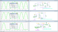
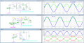
I need to simulate an half-wave and a full-wave rectifier. For the full-wave we'll use the middle point transformer and the bridge format.

I have 2 questions:

1 - How do I simulate a middle point transformer and how do I calculate the value of primary and secondary inductance so that I can have the correct transformation ratio?

2 - What are the formulas to calculate Vout DC and V out RMS in terms of integrals???

I've seen, in a google seach, that \(\frac{N_{1}}{N_{2}} = \sqrt{\frac{L_{1}}{L_{2}}}\)

But how do I calculate L1 and L2 exactly???

If I have 230V for the primary winding and 6V for the secondary winding, what would be L1 and L2 values?

I get strange values of \(\left (\frac{230}{6}\right ) = \frac{L_{1}}{L_{2}} \Leftrightarrow 1469.4 = \frac{L_{1}}{L_{2}}\).

It means that I need to make L1 = 1469.4, L2 = 0.5 and L3 = 0.5???
 
Last edited:

Thread Starter

PsySc0rpi0n

Joined Mar 4, 2014
1,762
I made this... Is this correct?

Edited;

I've changed the primary to 10H as you suggested! I get the same results and I guess I'm happy with it!


Now I just need to know how to calculate Vo RMS and Vo DC formulas in terms of integrals!
 

Attachments

Last edited:

ericgibbs

Joined Jan 29, 2010
18,848
The Vrms is 0.707 * Vpeak, to check your calculations press and hold down the keyboard 'Ctrl' key and left click on the Vo plot label.
 

Thread Starter

PsySc0rpi0n

Joined Mar 4, 2014
1,762
The Vrms is 0.707 * Vpeak, to check your calculations press and hold down the keyboard 'Ctrl' key and left click on the Vo plot label.
Yes, I know about that one... That's why I did Vin = 326V which matches 230V rms! That's what we usually get at our homes here in Portugal, Mr. EricGibbs!

I'm building the circuits for the full-wave rectifier using diode bridge!

Mr. EricGibbs, is there any special reason we should use he reference value of 10H for the primary winding?
 

Thread Starter

PsySc0rpi0n

Joined Mar 4, 2014
1,762
Ok, I'll watch it later... Can't watch it here at work...

Final results for 3 wave rectifiers... Let me know If is there anything wrong that can be improved!


Edited;

Should I change the V_in_sec and plot it referred to GND instead of N002???
If I plot it referred to GND, I'll see the negative wave semi-cycles cutted off to diode's Forward Voltage (inverted). If I plot it referred to N002 I won't be able to see the RMS value of ~6V for V_in_sec.
 

Attachments

Last edited:

ericgibbs

Joined Jan 29, 2010
18,848
They look OK to me.:)

For a practical circuit you should choose diodes which will be able to conduct the load current and have high enough reverse breakdown voltage.

The 1N4148 is only a signal diode specification
 

Thread Starter

PsySc0rpi0n

Joined Mar 4, 2014
1,762
They look OK to me.:)

For a practical circuit you should choose diodes which will be able to conduct the load current and have high enough reverse breakdown voltage.

The 1N4148 is only a signal diode specification
I've just noticed some non consistence in values I was supposed to see... I think It has something to do with RMS values... That always did some confusion in my head...

I want that Vout comes like V_in - Vγ (V_in - 2*Vγ for bridge setup) but that's not what I'm getting!!! Why?
 

Thread Starter

PsySc0rpi0n

Joined Mar 4, 2014
1,762
Ok, let me upload the circuits again because I made a few small changes.

I can't understand the V(out) values... I was expecting something around ~6V - 2*Vγ - R1*I1 for full-wave rectifier with bridge setup! But I don't know how to calculate current at R1.

Edited;

Once more I was using wrong values in L1 and L2 and also wrong inductors orientations!
Let me look again to V(out) values now!


Please check component values and verify I'm granting the same transformer conditions to all 3 circuits!
 

Attachments

Last edited:

Thread Starter

PsySc0rpi0n

Joined Mar 4, 2014
1,762
I've updated again my files... In the center tap circuit I was dividing both secondary windings values by 2 but I think I shouldn't because in each semi-cycle, the circuit has to be fed with the same voltage. So if I was using 3.405m for both winding s in the secondary, I was changing the original transform ratio!

Now I want to understand the RMS values given by LTSpice!
 

Attachments

ericgibbs

Joined Jan 29, 2010
18,848
Now I want to understand the RMS values given by LTSpice!
I guess you know that the Vfwd diode drop is approx 0.8V.? so the voltage to which you use to calc Vrms is Vsecondary peak voltage - Vfwd drop, then multiply by 0.707

Is this what you are asking.?
For the Centre Tap transformer circuit
 

Thread Starter

PsySc0rpi0n

Joined Mar 4, 2014
1,762
I guess you know that the Vfwd diode drop is approx 0.8V.? so the voltage to which you use to calc Vrms is Vsecondary peak voltage - Vfwd drop, then multiply by 0.707

Is this what you are asking.?
For the Centre Tap transformer circuit
What would be that voltage??? V(out)?
 

Thread Starter

PsySc0rpi0n

Joined Mar 4, 2014
1,762
Mr. EricGibbs, I managed to find the correct values of Vout RMS and Vout DC for half-wave rectifier but not for the other 2 circuits... Can you help???
 

ericgibbs

Joined Jan 29, 2010
18,848
hi Psy,
Using your LTS plots of the Vout, compare the Conduction period time to Non Conduction period, they are not the same, the shorter conduction time will effect your calculations.

Mr. EricGibbs, I managed to find the correct values of Vout RMS and Vout DC for half-wave rectifier but not for the other 2 circuits... Can you help???
Post your results so that we can see the problem in the calculations for those two circuits.
 

Thread Starter

PsySc0rpi0n

Joined Mar 4, 2014
1,762
hi Psy,
Using your LTS plots of the Vout, compare the Conduction period time to Non Conduction period, they are not the same, the shorter conduction time will effect your calculations.


Post your results so that we can see the problem in the calculations for those two circuits.
For Vout RMS I've used the first attached formula and for Vout DC, I've used the 2nd attached formula, where V out max is actually Vout max - Vγ.

My calcs resulted in Vout rms = 3.5575V (3.7834V in LTSPice) which I think it is acceptable!
And for Vout DC = 2.2628V (2.354V in LTSpice).

If images are not visible enough:

\(\displaystyle {V_{out\,rms} = \sqrt{\frac{1}{T}\cdot \left [ \int_{0}^{\frac{T}{2}}v^{2}_{out\,max}\cdot \sin^{2}\left ( \omega \cdot t \right )\,dt + \int_{\frac{T}{2}}^{T} 0^{2\,dt}\right ]} }\)

\(\displaystyle {v_{out\, DC} = \frac{1}{T}\left [ \int_{0}^{\frac{T}{2}} v_{out\,max} \cdot \sin\left ( \omega \cdot t \right ) \right ] }\)
 

Attachments

Thread Starter

PsySc0rpi0n

Joined Mar 4, 2014
1,762
Those are the formulas I'm using!
Also tried the simplified ones but no good!

Is there anyway I can check the Vmax of any waveform in LTSpice rather than using cursors and sliding them manually until I find the peak value????

I've been doing that way. Use cursor1, look for the max value of Vout, subtract Vγ and divide the result by 2 or √2 for half or full-wave...
 

ericgibbs

Joined Jan 29, 2010
18,848
I do not understand what you asking, you say you have tried the formula's but they are no good.?
What does that mean.??? no good.
The cursors in LTS are provided to enable you to take measurements from the plots.

Perhaps another member may be able to understand what is your problem.:(
 
Top