Running 1 12v motor from 2 different power sources

Tonyr1084

Joined Sep 24, 2015
9,744
With the drawing from post #20 - couldn't you just program your TCR to switch on immediately, giving you full power but then after X time it switches off and drops the contacts back to the position shown? Your TCR will not be drawing any power for the duration of the operation. During the time period the PWM will not be in operation. Only when the TCR drops out will the PWM switch on and control the motor speed.

Am I missing something?
 

MisterBill2

Joined Jan 23, 2018
27,741
The problem started with post #1, which was incorrect in the connections.
At that point no mention was made that the PWM control module switched the negative side of the motor feed.
A single DPDT relay connecting both sides of the motor to the selected source would have been the correct choice.
Admittedly I was in error for not calling out the fault at that point, but evidently others did not see it either. So we all have a chance to learn something .
 

ElectricSpidey

Joined Dec 2, 2017
3,342
Final drive FET.

N-Channel = low side switching.
P-channel = high side switching.

From my experience most commercial PWM motor drives use low side switching, but it should still be confirmed.
 

DC_Kid

Joined Feb 25, 2008
1,242
Did I miss something? Where did we discuss FET's?
Because it matters how the motor is connected to batt.

One easy way to verify, ohm the POWER+ and MOTOR+ terminals on the controller. If it's N fet then we should expect those two contacts to be zero ohms and the PWM drives a FET that sinks the current (nFET config). At least that would be the simplest way to make a controller like that, perhaps I expect it to be that way.

If it's nFET drive then all that is needed is a SPDT relay to throw the neg side of the motor between controller-motor-neg or direct to ground. There is no need to switch out the controller power, you only need to direct where the neg side of the motor is going.
 
Last edited:

Thread Starter

titans7

Joined Dec 18, 2024
38
You guys are amazing at what you know and do.

1738082362420.png

Works!!!

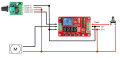
This is my actual setup. I have the PWM set at 5 volts of output.
Test run:
-Set timer for 15 sec
-Press push button and motor is running full speed.

Voltage checks:
DC+ and NC- is 12v
DC+ and COM- is 12v
DC+ and NO- is 5v

-15 sec counts down to zero, relay swaps to NO
-motor slows down to a crawl (very nice !!!)

Voltage checks:
DC+ and NC- is 12v
DC+ and COM- is now 5v (again, Very Nice!!!)
DC+ and NO- is 5v

I can't thank you guys enough for yet another fun experiment.
 

BobTPH

Joined Jun 5, 2013
11,573
You guys beat me too it and why I didn't catch that is crazy. The PWM controller states on the box "pwm VOLTAGE controller"
No. PWM does not change the voltage. It switches the original voltage (12V) on and off rapidly, this cutting the average power. The multimeter reads 5V because it averages the voltage over time. But the voltage is actually swinging between 0V and 12V.
 

Thread Starter

titans7

Joined Dec 18, 2024
38
I actually just took it a step further and added another relay (not timed). This relay is triggered by an NPN proximity sensor and thus shuts the motor completely off.

-So, timer is triggered and runs motor at full voltage
-timer times out, swaps state, and runs on lower voltage from PWM
-new added relay allows motor to run at lower voltage until proximity sensor is detected
-signal is sent back to newly added relay and thus shuts off motor.

Happy, Happy Happy.
 

DC_Kid

Joined Feb 25, 2008
1,242
You guys are amazing at what you know and do.
Works!!!
I suspect, you don't need to wire in the MOTOR+ on the controller, you already feed the motor directly from the 12v+ supply, at least that's what your last wire diagram shows.

-timer times out, swaps state, and runs on lower voltage from PWM
As mentioned, it's not really lower voltage, it's your 12v being chopped up into a duty cycle. You might also be interested in knowing the actual PWM frequency used. DC motors are touchy when it comes to the frequency used. Did that controller come with any documentation saying what frequency the PWM runs at? Probably not a bad idea to place a diode (reversed) across motor terminals to prevent any kickback voltage from punching a hole on controller silicon.
 
Last edited:

Tonyr1084

Joined Sep 24, 2015
9,744
PWM doesn't vary the voltage it varies the time between ON and OFF. You get an Average or apparent voltage. What you're really seeing is akin to 12 volts half the time on and half the time off - it appears to be 6 volts even though it's not. Power is a better term for PWM output as opposed to calling it voltage.
 

MisterBill2

Joined Jan 23, 2018
27,741
REally, to cover all of the possible variations, A DOUBLE POLE double throw relay is required to assure complete isolation between the two power sources. IF that had been selected initially that would have totally avoided the problems.
 
Top