To further expand on what Ken said there may also be an issue of the feeble lumen's that neon lamps produce. I've never measured the NE2 but they're not exactly noted as being a Q-Beam. Data sheet anyone?
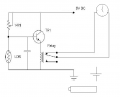
LDR's are not noted for their fast response time, so yeah, that might be an advantage with a neon bulb. I would suggest that you bench test your circuit to insure that and to also insure that the neon bulb will drive the LDR. Other than that, your circuit looks fine. I'm assuming that you're using the NC contacts, where Q1 & Relay are off when the neon is on.
EDIT: Oops! I forgot. You need a protection diode across the relay coil!!!
Some thoughts:
1. I assume the run time is relative short compared to the non-run time. With that circuit the 9V battery is driving the relay during the non-run time. Swapping the pot and the LDR will have it driving the relay during the shorter non-run time.
2. 9V batteries has very little capacity and won't last long driving a relay. I would suggest switching to four 1.5V AA batteries (6V) and use a 5V reed relay.
3. Because the clock draws so little current, I would just tap one of the 1.5V batteries in the 6V string to drive the clock.
4. The relays give a nice definite on-off, but with a little bench testing, an added transistor might be used to replace the relay and draw much less current.
5. Then again, I would probable just use a LM311 comparator circuit.
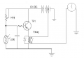
This is what I had in mind. R1 =~ LDR1 dark resistance. R2 sets trip point when LDR1 is lit. I haven't tried this with a neon lamp, but I think the slow response time of the LDR and the adjustment of R2 could handle that. I also might add a capacitor across LDR1 to filter out the 120Hz ripple. Maybe something between 4.7uF and 100uF.
Some thoughts:
1. I assume the run time is relative short compared to the non-run time. With that circuit the 9V battery is driving the relay during the non-run time. Swapping the pot and the LDR will have it driving the relay during the shorter non-run time.
<snip>Ken
Love your ideal kmoffet, but I have 50 5v reed relays waiting to be used (sigh) Thanks for all the help cdirve. Ill build this and check it out and then Ill come back for more abuse (LOL)
You guys are great and very knowledgeable
blofish, before you start building this I think it would be a good idea to test your LDR with the freezer neon light. Tape it to the light with electrical tape to block out ambient light. Measure the dark resistance with an Ohmmeter and then with the light on. Use the 'Power' light so you can unplug the freezer measure, replug and measure again. This way you won't have to wait for the 'Run' light to come on.
BTW, I think you can eliminate the relay. The little clock I described earlier draws so little that an NPN should be capable of driving it directly. This will also save you battery power and enable you to use one 1.5V cell.
BTW, these are the quartz clocks I'm talking about. They're very easy to use. Heck, my wife needle points clock faces for them. If she can put them together anyone can. After all, it's now been 38 years and she still hasn't grasped the concept of "Righty - Tighty - Lefty - Loosey". Which is a mind blower, since she was a senior programmer analyst in COBOL, Fortran, Assembly plus a host of others.
I tested a LDR on the RUN light and it worked great, GL5539, with the light off R was >2Mohm and lite it was about 32Kohms... Ill bread board this soon and post the results
Freezers are designed without a lot of excess capacity. The recorder charts I've seen show about 50% run time for an empty freezer in the repair shop. Adding a serious load would put the compressor into 100% run for several hours. Then, it would revert to about 50% run time because the refrigeration system returns to only compensating for heat passing through the outer case of the machine, except that with a load, the time periods will be longer. The duty cycle will be the same.
As a repairman, I open these things up in a matter of seconds and I am amazed at the amount of work you are willing to do to avoid putting a pair of alligator clips on the compressor terminals.
It is rare that I question the OP's intent, but this one is so different from my point of view that it has provoked me out of my silence.
 Facebook
 Google
 GitHub
 Linkedin
 Data sheet anyone?